We Service All Water Softeners and We Sell Parts for All Water Softeners
We will service all water softeners.
There was a survey that was performed in connection with the Central Arizona Salinity Study (CASS) which studied water softener penetration in the Phoenix Arizona metro area. At the time the survey was conducted (2004) it was estimated that the penetration of water softeners was 51 percent – for homes built since the year 2000 – and it was 47 percent for homes built in the 1990’s. The CASS is now estimating that about 26 percent of all homes in the Phoenix area have water softeners. (this is my information source: e-mail dated 09.09.13 from David Perry ‘Executive Director of the Arizona Water Quality Association’)
In our effort to be the best water conditioning company in the world; we want to become service experts on all water softener units and all water filtration units ‘residential and commercial’. We wish to carry the most common parts (with an emphasis on recycled parts) for these units and provide service to these units. If we don’t have the parts – we will seek and research the parts and procure them for you. We liken this approach to adopting orphan water treatment equipment. We love the people we meet utilizing this approach. If we can’t fix your unit – we will learn or suggest to you the alternative options to economically provide you soft water. We are very upfront business people and water treatment professionals. We will always tell you that we have developed some unique rental water treatment approaches that represent our three operating tenants: 1. To raise the standard of our water treatment industry 2. To aggrandize our client relationships and 3. To develop a sustainable approach to water treatment that will benefit our client’s budgets and positively impact higher quality results for water treatment in our region.
Our approach is to earn your trust by adding the highest value to your existing water treatment equipment.
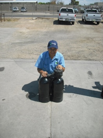
Here are pictures of some of the units we service. Our onus is to continue to increase our water treatment service repertoire and add the pictures of all these different units. If there is a certain type of water treatment equipment being installed in the Phoenix Metro area of Arizona; we will seek to own it – explicate this – dissect this and sell the parts. Once we learn the unit – we will want more of these units (to gain more individual parts on each different type of unit) to share with you. We hope to increase your water treatment value and experience with this approach.
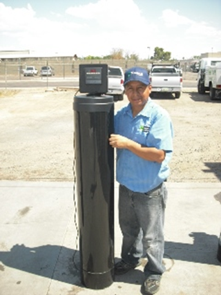
#1
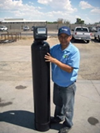
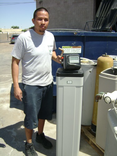
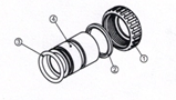
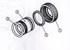
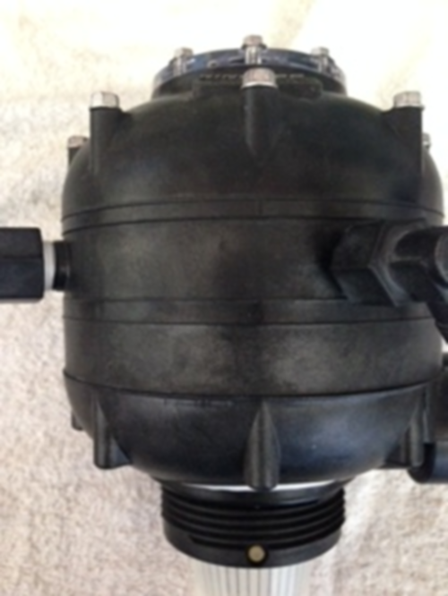
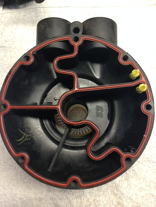
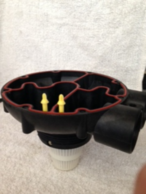
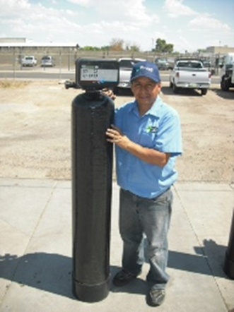
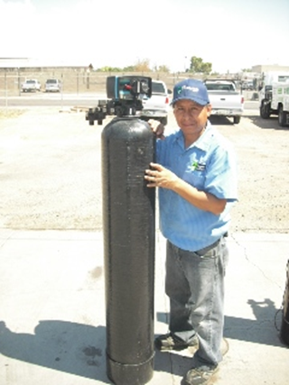
08.08.14 These are two images of Clack Water Softeners displayed by Francisco and Marco. We carry all the components and parts to service these water softeners. These are good water softeners. When one of our clients purchase a water softener; this is the brand of valve that we install. We build our own water equipment, deliver, install, service and customer service this equipment. We feel this is one of our success formulas. We are a one stop shop. The same people you talk to on the phone will be the same people who build your unit and install and service this unit for you.
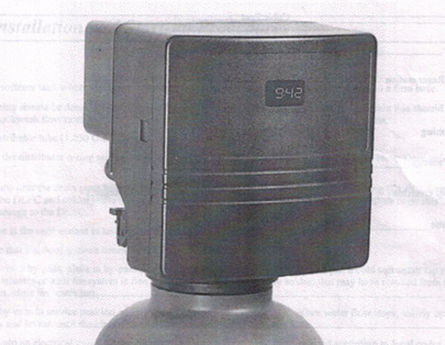
11.18.15 12:34 PM
Clack WS 1 water softener valve – parts and operational manual
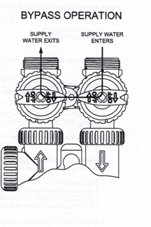
Bypass Valve
The bypass valve is typically used to isolate the control valve from the plumbing system’s water pressure in order to perform control valve repairs or maintenance. The WS 1 bypass valve is particularly unique in the water treatment industry due to its versatility and state of the art design features. The 1″ full flow bypass valve incorporates four positions including a diagnostic position that allows service personal to work on a pressurized system while still providing untreated bypass water to the facility or residence. It’s completely non-metallic, all plastic design allows for easy access and serviceability without the need for tools.
The bypass body and rotors are glass filled Noryl and the nuts and caps are glass filled polypropylene. All seals are self-lubricating EPDM to help prevent valve seizing after long periods of non-use. Internal 0-rings can easily be replaced if service is required.
The bypass consists of two interchangeable plug valves that are operated independently by red arrow shaped handles. The handles identity the flow direction of the water. The plug valves enable the bypass valve to operate in four positions.
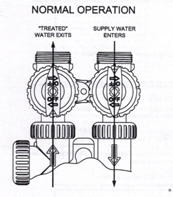
- Normal Operation Position: The inlet and outlet handles point in the direction of flow indicated by the engraved arrows on the control valve. Water flows through the control valve during normal operation and this position also allows the control valve to isolate the media bed during the regeneration cycle.
 2. Bypass Position: The inlet and outlet handles point to the center of the bypass, the control valve in isolated from the water pressure contained in the plumbing system. Untreated water is supplied to the plumbing system.
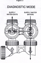
 3. Diagnostic Position: The inlet handle points in the direction of flow and the outlet handle points to the center of bypass valve, system water pressure is allowed to the control valve and the plumbiiig system while not allowing water to exit from the control valve to the plumbing.
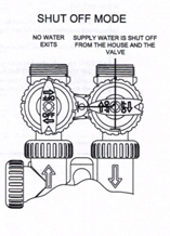
 4. Shut Off Position: The inlet handle points to the center of the bypass valve and the outlet handle points in the direction of flow, the water is shut off to the plumbing system. If water is available on the outlet side of the softener it is an indication of water bypass around the system (i.e. a plumbing connection somewhere in the building bypasses the system).
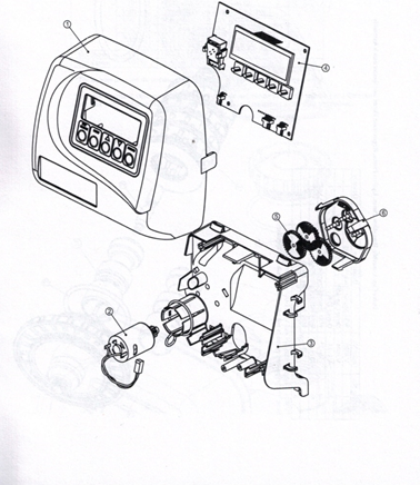
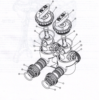
Front Cover and Drive Assembly for WS1 Clack water softener valve
Drawing No. Order No. Description Quantity
1 V3175-01 WS 1 Front Cover ASY 1
2 V3107-01 WS 1 Motor 1
3 V3106-01 WS 1 Drive Bracket & Spring Clip 1
4 V3108 WS 1 PC Board 1
5 V3110 WS 1 Drive Geart 12×36 3
6 V3109 WS 1 Drive Gear Cover
V3002 WS 1 Drive ASY
Not Shown 173186 WS Transformer ttOV-t2V
* Drawing number parts 2 through 6 may be purchased as a complete assembly, part ‘5/3002.
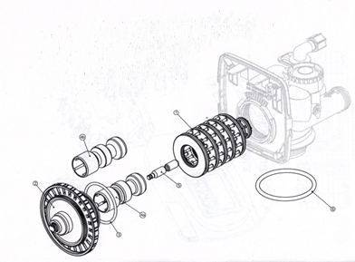
Drive Cap Assembly, Dowoflow Piston, Upflow Piston, Regenerant Piston and Spacer Stack Assembly for WS1 Clack Water Softener
Drawing No. Order No. Description Quantity
1 V3005 WSI Spacer Stack Assembly 1
2 V3004 Drive Cap ASY 1
3 V3135 0-ring 228 1
4a V3011* WS 1 Piston Downflow ASY 1
4b V301 1-01 WS1 Piston Upflow ASY 1
5 V3174 WS 1 Regenerant Piston 1
6 V3180 0-ring 337 1
V3O11 is labeled with DN and V3011-01 is labeled with UP.
Note: The regenerant piston is not used in backwash only applications.
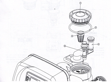
Injector Cap, Injector Screen, Injector, Plug and 0-Ring
Drawing No. Order No. Description Quantity
1 V3176 Injector Cap 1
2 V3152 0-ring 135 1
3 V3177 Injector Screen 1
4 V3010-IZ WS 1 Injector ASY Z Plug 1
V3010-1A WS1 INJECTOR ASYABLACK
V3010-IB WS1 INJECFORASY B BROWN
V3010-IC WS1 INJECTOR ASY C VIOLET
V30I0-ID WS1 INJECTOR ASYDRED
V3010-1E WS1 INJECTOR ASYE WHITE
5 V3010-IF WS1 INJECTOR ASYFBLUE
V3010-IG WS1 INJECTOR ASY G YELLOW
V3010-1H WS1 INJECTOR ASYHGREEN
V3010-1I WS1 INJECTOR ASY I ORANGE
V3010-1J WS1 INJECTOR ASY J LIGHT BLUE
V3010-1K WS1 INJECTOR ASY K LIGHT GREEN
Not Shown V3170 0-ring011
Not Shown V3171 0-ring 013
*The injector ping and the injector each contain one 011 (tower) and 013 (upper) 0-ring.
Note: For downflow, injector is located in the down hole and injector plug in the up hole. For a filter that only backwashes, injector plugs are located in both holes, and regenerant piston must be removed.
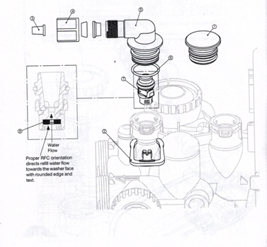
Refill and Refill Port Plug
Drawing No Order No. Description Quantity
1 V3195-01 WS Refill Port Plug ASY This part is required for backwash
only systems
2 H4615 Elbow Locking Clip
3 JCP-P-6 Polytube insert 3/8
4 JCPG-6PBLK Nut 3/8
5 014613 Elbow Cap 318
6 V3163 0-ring019 1
7 V3165_01* WS 1 RFC Retainer ASY
8 V3182 WS1RFC 1
Not Shown H4650 Elbow 1/2″ with nut and insert Option
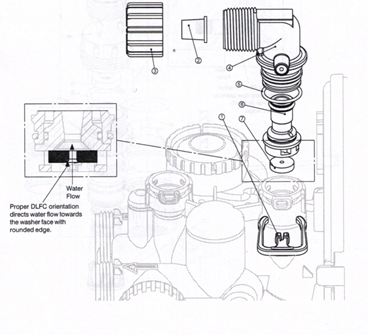
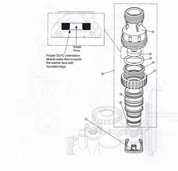
Drain Line-3/4″
Drawing No. Order No. Description Quantity
I 114615 Elbow LockingClip 1
2 PKPIOTS8-BULK Polytube insert 5/8 Option
3 V3I92 WS1 Nut 3/4 Drain Elbow Option
4 V3158-01 WS 1 Drain Elbow ¾ Male ASY 1
5 V3163 0-ring 019 1
6 V3159-Ol WS1 DLFC Rotairrr ASY 1
VS 162-007 WS DLFC 0.7 rpm for 3/4
V3162-010 WS1 DLFC I.) Gpm for 3/4
V3162-013 WS 1 DLFC 1.3 gym for 3/4
V3162-0I7 WS1 DLFC l.7gimc for 3/4 0ne
V3162-022 WS1 DLFC 2.2 ppm for 3/4 DLFC
V3162-027 WS1 DLFC 2.7 gpm for /3/4 must be
used if ¾”
fitting is used
7 V3I62-032 WS1 DLFC 3.2 fgpm or 3/4
VS l62-042 WS1 DLFC 4.2 gym for 314
V3162-053 WS1 DLPC 5.3 gym for 3/4
V3162-065 WS1 DLFC 6.5 gym for 3/4
VS 3162-075 6’Sl DLFC 7.5 gym for 3/4
V3162-090 WSI DLFC 9.0 ppm for 3/4
V3162-I00 WSI DLFC 10.0 gpm for 3/4
Valves are shipped without drain line flow control (DLFC) —install DLPC before using. Valves are shipped without ¾” nut for drain elbow (polytube installation only) and 5/8″ polytube installation only).
Drawing No. Order No. Description Quantity
1 H4615 Elbow Locking Clip 1
2 V3008-02 WS Drain FTG 1 Straight 1
3* V3166 WS 1 Drain FTC Body 1 1
4° V3167 WS1 Drain FTG Adaptor 1 1
5° V3163 0-ring 019 1
6° V3150 WS1 Split Ring 1
7° V3151 WS1 Nut 1” QC 1
8* V3105 O-ring 215 1
V3190-090 WS 1 DLFC 9.0 gpm for 1
V5190-100 WS 1 DLFC 10.0 gpm for 1 One
V3190-110 WS 1 DLFC 11.0 gpm for 1 DLFC
V3190-130 WS 1 DLFC 13.0 gpm for 1 must be
V3190-150 WS1 DLFC 15.0 gym for 1 used if
V3190-170 WS 1 DLFC 17.0 gym for 1 1″ fitting
V3190-200 WS 1 DLFC 20.0 gym for 1 is used
V3190-250 WS1 DLFC 25.0 gym for 1
Can be ordered us a set order number V3008-02, description: WS1 Drain FTG 1 Straight.
Water Meter and Meter Plug
Drawing No. Order No. Description Quantity
1 V3151 WS1 Nut 1” QC 1
2 V3003° WS1 Meter ASY 1
3 V3118-01 WS1 Turbine ASY 1
4 V3105 0-ring 215 1
5 V3003-01 WS 1 Meter Plug ASY 1
*Order number V3003 includes V3118-01 and V3105.
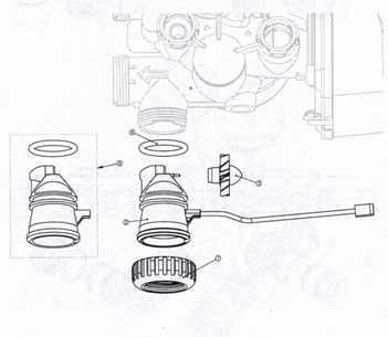
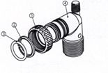
Installation Fitting Assemblies
Order No: V3007
Description: WS1 Fitting 1” PVC Male NPT Elbow Assembly
Drawing no order no description quantity
1 V3151 WS1 Nut 1 “ Quick Connect 2
2 V3l50 WS 1 Split Ring 2
3 V3105 O-Ring 215 2
4 V3149 WS1 Fitting 1 PVC Male NPT Elbow 2
Order No: V3007
Description: WS1 Fitting 1” PVC Male NPT Elbow Assembly
Drawing no order no description quantity
1 V3151 WS1 Nut 1” Quick Connect 2
2 V3150 WS1 Split Ring 2
3 V3105 O Ring 215 2
4 V3149 WS1 Fitting 1 PVC Male NPT Elbow 2
Order No: V3507-02
Description: WSI Fitting 1″ Brass Sweat Assembly
Drawing no order no description quantity
1 V3151 WS1 Nut 1” Quick Connect 2
2 V3150 WS1 Split Ring 2
3 V3105 O-Ring215 2
4 V3188 WS1 Fitting 1” Brass Sweet 2
Order No: V3007-03
Description: WSJ Fitting 3/4’” Brass Sweat Assembly
Drawing no order no description quantity
1 V3151 WS1 Nut 1” Quick Connect 2
2 V3150 WS1 Split Ring 2
3 V3105 O-Ring 215 2
4 V3188-01 WS 1 Fitting ¾ Brass Sweat 2
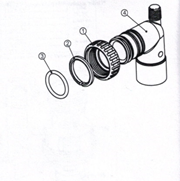
Bypass Valve
Drawing No. Order No. Description Quantity
1 V3151 WS1 Nut 1″ Quick Connect 2
2 V3150 WS1 Split Ring 2
3 V3105 O-Ring 2I5 2
4 V3145 WS1 Bypass 1″ Rotor 2
5 V3146 WS1 Bypass Cap 2
6 V3147 WS1 Bypass Handle 2
7 V3148 WS1 Bypass Rotor Seal Retainer 2
8 V3152 0 -ring 135 2
9 V3152 0-ring 112 2
10 V3156 O-ring 214 2
(Not Shown) Order No. V3191-01, Description: WS1 Bypass Vertical Adapter Assembly
Order No. Description Quantity
V3151 WS1 Nut 1″ Quick Connect 2
V3150 WS1 Split Ring 2
V3105 0-Ring 215 2
V3191-01 WS1 Bypass Vertical Adapter Assembly 2
Service Instructions
Drive Assembly
Remove the valve cover to seems the drive assembly
Disconnect the power source plug (black wire) from the PC board prior to disconnecting the motor or water meter plugs from the PC board. The motor plug connects to the two-pin jack on the left-hand side of the PC board. The power source plug connects to the four-pinjack. The four-pinjack is between the two-pin and three-pin jacks. The water meter plug (gray wire) connects to the three-pin jack on the far right-hand side of the PC board.
The PC board can be removed separately from the drive bracket but it is not recommended. Do not attempt to remove the display panel from the PC board. Handle the board by the edges. To remove the PC board from the drive bracket, unplug the power, water meter and motor plugs from the PC board. Lift the middle latch along the top of the drive bracket while pulling outward on the top of the PC board. The drive bracket has two plastic pins that fit into the holes on the lower edge of the PC board. Once the PC board is tilted about 45 from the drive bracket it can be lifted off of these pins. To reinstall the PC board, position the lower edge of the PC board so that the holes in the PC board lineup with the plastic pins. Push the top of the PC board towards the valve until it snaps under the middle latch, weave the power and water meter wires into the holders and reconnect the motor, water meter and power plugs.
The drive bracket must be removed to access the drive cap assembly and pistons or the drive gear cover. It is not necessary to remove the PC board from the drive bracket to remove the drive bracket. To remove the drive bracket start by removing the plugs for the power source and the water meter. Unweave the wires from the side holders. Two tabs on the top of the drive back plate hold the drive bracket in place. Simultaneously lift the two tabs and gently ease the tap of the drive bracket towards your body. The lower edge of the drive bracket has two notches that rest on the drive back plate. Lift up and outward on the drive bracket to disengage
the notches.
To reassemble seat the bottom of the drive bracket so the notches are engaged at the bottom of the drive back plate. Push the top of the drive bracket towards the two latches. The drive bracket may have to be lifted slightly to let the threaded piston rod pass through the hole In the drive bracket Maintain a slight engaging force on top of the drive bracket while deflecting the bracket slightly to the left by pressing on the side of the upper right corner. This helps the drive gears mesh with the drive cap assembly. The drive bracket is properly seated when it snaps under the latches on the drive back plate. If resistance is felt before latching, then notches are not filly engaged, the piston rod is not in hole, the wires are jammed between the drive bracket and drive buck plate, or the gear is not engaging the drive cap assembly.
To inspect drive gears, the drive gear cover needs to be removed. The drive gear cover is held in place on the drive bracket by three clips. The largest of the three clips is always orientated to the bottom of the drive bracket. Before trying to remove the drive gear cover, the drive bracket must be removed from the drive back plate. The drive gear cover can be removed from the drive bracket without removing the motor or the PC board. Simultaneously, push in and down on the large clip at the bottom and the clip on the left-hand side of the drive bracket behind the PC board. Keep your other fingers behind the drive gear cover so the drive gears do not drop on the ground.
Replace broken or damaged drive gears. Do not lubricate any of the gears. Avoid getting any foreign matter on the reflective coating became dirt or oils may interfere with pulse counting.
The drive gear cover only fits on one way, with the large clip orientated towards the bottom. If all three clips are outside of the gear shroud on the drive bracket the drive gear cover slips easily into place.
The drive bracket does not need to be removed from the drive plate if the motor needs to be removed. To remove the motor, disconnect the power and motor plugs from the jacks on the PC board. Move the spring clip loop to the right and hold. Rotate the motor at least a% turn in either direction before gently pulling on the wire connectors to remove the motor. Pulling directly on the wires without rotating the motor may break the wires off the motor.
Replace the motor if necessary. Do not lubricate the motor or the gears. When reinstalling the motor gently turn the motor while inserting so that the gear on the motor meshes with the gears under the drive gear cover and the small plastic bulge engages one of the slots on the motor housing. Reconnect the motor plug to the two pronged jack on the lower left hand side of the PC board. If motor will not easily engage with drive gear when reinstalling, lift and slightly rotate motor before reinserting.
Replace the valve cover. After completing any valve maintenance, press and hold NEXT and REGEN bottom for 3 seconds or unplug power source jack (black wire) and plug back in. This resets the electronics and establishes the service piston position. The display should flash all wording, then flash the soft ware version (e.g. 154) and then reset the valve to the service position.
Drive Can Assembly Main Piston and Regenerant Piston
The drive assembly must be removed to access the drive cap assembly. The drive cap assembly most be removed to access the piston(s). The drive cap assembly is threaded into the control valve body and seals with an o-ring. To remove the drive cap assembly use the special plastic wrench or insert a ¼’ to /i flat bladed screwdriver into one of the slots around the top 2″ of the drive cap assembly so it engages the notches molded into the drive back plate around the top 2′ of the piston cavity. The notches are visible through the holes. Lever the screwdriver so the drive cap assembly turns counter clockwise. Once loosened unscrew the drive cap assembly by hand and pull straight out.
The drive cap assembly contains the drive cap, the main drive gear, drive cap spline, piston rod and various other parts that should not be dissembled in the field. The only replaceable part on the drive cap assembly is the 0-ring. Attached to the drive cap assembly is the main piston (down flow or up flow) and if a regenerant is used, a regenerant piston.
The regenerant piston (the small diameter one behind the main piston) is removed from the main piston by unsnapping it from its latch. Chemically clean in dilute sodium bisulfite or vinegar or replace the regenerant piston if needed. To remove the main down flow or up flow piston fully extend the piston rod and then unsnap the main piston from its latch by pressing on the side with the number. Chemically clean in dilute sodium bisulfite or vinegar or replace the main piston.
Reattach the main piston to the drive cap assembly. Reattach the regenerant piston (if needed) to the main piston. Do not lubricate the piston rod, main piston or regenerant piston. Lubricant will adversely affect the red or clear lip seals. Reinsert the drive cap assembly and piston into the spacer stack assembly and hand tighten the drive cap assembly. Continue to tighten the drive cap assembly using a screwdriver as a ratchet until the black o-ring on the spacer stack assembly is no longer visible through the drain port. Excessive force can break the notches molded into the drive back plate. Make certain that the main drive gear still turns freely. The exact position of the piston is not important as long as the main drive gear turns freely.
Reattach the drive assembly to the control valve and connect all plugs. After completing any valve maintenance, press and hold NEXT and REGEN buttons for 3 seconds or unplug power source jack (black wire) and plug back in. This resets the electronics and establishes the service piston position. The display should flash all wording, then flash the soft ware version (e.g. 154) and then reset the valve to the service position.
spacer stack assembly
To access the spacer slack assembly remove the drive assembly, drive cap assembly and piston. The spacer stack assembly can be removed easily without tools by using thumb and forefinger. Inspect the black 0-rings and red or clear lip seals for wear or damage Replace the entire stack if necessary. The spacer stack assembly has been 100% tested at the factory to insure proper orientation of one way seals. Do not disassemble the stack.
The spacer stack assembly maybe chemically cleaned (dilute sodium bisulfite or vinegar) or wiped with a soft cloth.
The spacer stack assembly can be pushed in to the control valve body bore by hand. Since the spacer stack assembly can be compressed it is easier to use a blunt object (5/8″ to 1-1/8″ in diameter) to push the center of the assembly into the control valve body. – The assembly is properly seated when at least four threads are exposed (approximately 5/8″). Do not force the spacer stack assembly in. The control valve body bore interior can be lubricated with silicone to allow for easy insertion of the entire stack. Do not use silicone or any other type of lubricant on the red or clear lip seals or the piston.
Reattach the drive cap assembly and piston(s) and the drive assembly.
After completing any valve maintenance, press and hold NEXT and REGEN buttons for 3 seconds or unplug power source jack (black wire) and plug back in. This resets the electronics and establishes the service piston position The display should flash all wording, then flash the soft ware version and then reset the valve to the service position.
Injector Can. Screen Injector Plug and Injector
Unscrew the injector cap and lift off. Loosen cap with special plastic wrench or pliers if necessary. Attached to the injector cap is a screen. Remove the screen and clean if fouled.
The plug and/or injector can be pried Out with a small screwdriver. The plug can be wiped clean. If the plug leaks replace the entire plug. The injector consists of a throat and a nozzle. Chemically clean the injector with vinegar or sodium bisulfite. The holes can be blown out with air. Both pieces have small diameter holes that control the flow rates of water to insure that the proper concentration of regenerant is used. Sharp objects, which can score the plastic, should not be used to clean the injector. Scoring the injector or increasing the diameter of the hole could change the operating parameters of the injector.
Two holes are labeled DN and UP. Check for compliance with one of the following:
- for down flow systems, the appropriate size injector in located in the “DM’ hole, a plug is in the “UP” hole and that the piston is a combination of the down flow main piston and the regenerant piston.
- for up flow systems, the appropriate size injector is located in the “UP” hole, a plug is in the “Whole and that the piston is a combination of the up flow main piston and the regenerant piston; or
- for backwash only systems, a plug is in the “DN” hole and in the “UP” hole, and that the piston only has a down flow main piston (the regenerant piston must be removed) and a plug is in the refill flow control position.
Push the plug(s) and/or injectors firmly in place, replace the screen and hand tighten the injector cap.
Refill Flow Contrpl Assembly or-Refill Port Plug
To clean or replace the refill flow control, pull out the elbow-locking clip and then pull straight upon the elbow. Replace the elbow locking clip in the slot so that it is not misplaced. Twist to remove the white flow control retainer. The flow control can be removed by prying upward through the side slots of the retainer with a small blade flat screwdriver.
Chemically clean the flow control or the white flow control retainer using dilute sodium bisulfite or vinegar. Do not me a wire brush. If necessary, replace the flow control, wring on the flow control retainer, or the 0-ring on the elbow.
Reseat the flow control so the rounded end is visible in the flow control. Reseal the white flow control retainer by pushing the retainer into the elbow until the wring seats. Remove locking clip, push down on elbow to reseat and insert locking clip.
Do not use Vaseline, oils, or other unacceptable lubricants on o-rings. A silicon lubricant may be used on the n-ring on the elbow or the white retainer.
Water Meter or Meter Plug
The water meter assembly is connected to the PC board by a wire. If the entire water meter assembly is to be replaced, remove the control valve cover and remove the power source and water meter plugs from the PC board. Unlatch the drive assembly and lean it forward. Unthread the water meter wire from the side of the drive assembly and through the drive back plate. To reinstall, rethread the water meter wire through the drive back plate and the side of the drive assembly. Reattach the drive assembly and the water meter and power plugs.
If no water meter wire is visible, then a plug is installed not a water meter.
The water meter wire does not need to be removed from the PC board if the water meter is only being inspected and cleaned. To remove the water meter assembly, unscrew the meter capon the left side of the control valve. Pliers maybe used to unscrew the nut if necessary.
With the nut removed, a slot at the top of the water meter is visible. Twist a flat blade screwdriver in the slot between the control valve body and the meter. When the meter is part way out it is easy to remove the water meter from the housing. Once the water meter is removed from the control valve body, use your fingers to gently pull forward on the turbine to remove it from the shaft.
Do not use a wire brush to clean. Wipe with a clean cloth or chemically clean in dilute sodium bisulfite or vinegar. The turbine can be immersed in the chemical. Do not immerse electronics. If the turbine is scored or damaged or the bearings on the turbine are worn replace the turbine.
Do not lubricate the turbine shaft. The turbine shaft bearings are prelubricated Do not use Vaseline, oils, or other unacceptable lubricants on the o-ring. A silicon lubricant may be used on the black 0-ring.
Snap the turbine on the shaft and reinsert the water meter into the side slot. Hand tighten the nut. Do not use a pipe wrench to tighten nut.
Bypass Valve
The working parts of the bypass valve are the rotor assemblies that are contained under the bypass valve caps. Before working on the rotors, make sure the system is depressurized. Turn the red arrow shaped handles towards the center of the bypass valve and back to the arrow direction several times to ensure rotor is turning freely.
The nuts and caps are designed to be unscrewed or tightened by hand. If necessary a pliers can be used to unscrew the nut or cap. Do not uses pipe wrench to tighten or loosen nuts or caps. Do not place screwdriver in slots on caps and/or tap with a hammer.
To access the rotor, unscrew the cap and lift the cap, rotor and handle Out as one unit. Twisting the unit as you pull it out will help to remove it more easily. There are three 0-rings: one under the rotor cap, one on the rotor stem and the rotor seal. Replace worn 0-rings. Clean rotor. Reinstall rotor.
When reinstalling the red arrow handles be sure that:
- 0-rings on both rotors face to the right when being viewed from the front of the control valve when the handle pointers are lined up with the control valve body arrows; or
2 Arrows point toward each other in the bypass position.
Since the handles can be pulled off, they could be accidentally reinstalled I 80°° from their correct orientation. To install the red arrow handles correctly, keep the handles pointed in the same direction as the arrows engraved on the control valve body while tightening II bypass valve caps.
After completing any valve maintenance, press and hold NEXT and REGEN buttons for 3 seconds or unplug power source jack (black wire) and plug back in. This resets the electronics and establishes the service piston position. The display should flash all wording, then flash the software version (e.g. 154) and then reset the valve to the service pdsition.
Troubleshooting Procedures
Problem Possible Cause Solution
- Timer does not display time of day
- Transformer unplugged a. Connect power
- No electric power at outlet – b. Repair outlet or use working
outlet
- Defective transformer c. Replace transformer
- Defective PC board d. Replace PC board
- Timer does not display a. Switched outlet a.Use uninterrupted outlet
correct time of day
- Power outage b. Reset time of day
- Defective PC board c. Replace PC board
- No softening/filtering display when water is flowing
- Bypass valve in bypass position a.Put bypass valve in service position
- Meter connection disconnected b. Connect meter to PC board
- Restricted/stalled meter turbine c. Remove meter and check for rotation or foreign
material
- Defective meter d. Replace meter
- Defective PC board e. Replace PC board
- Control valve regenerates at wrong time of day
- Power outages a. Reset control valve to correct time of day
- Time of day not set correctly b. Reset to correct time of day
- Time of regeneration incorrect c. Reset regeneration time
- Control valve set at “ on 0″ d. Check control valve set-up procedure
(immediate regeneration) regeneration time option
- Control valve set at NORMAL + c. Check control valve set-up procedure
on 0 regeneration time option
- ERROR followed by code number
Error Code 1001 -Unable to recognize start of regeneration
Error Code 1002— Unexpected stall
Error Code 1003 – Motor ran to long, limed out trying to reach next cycle position
Error Code 1004- Motor ran to long, timed out trying to reach home position.
If other Error Codes display contact the factory.
- Control valve has just been a. Press NEXT and REGEN for 3
serviced seconds or unplug power source jack
(black wire) and plug back in to reset
control valve
- Foreign matter is lodged in b. Check piston and spacer stack
control valve assembly for foreign matter
- High drive forces on piston c. Replace piston(s) and spacer stack assembly
- Control valve piston not in home position d. Press NEXT and REGEN for 3 seconds or
unplug power source jack (black wire) and
plug back in to reset control valve
- Motor not inserted filly to engage e. Check motor and wiring.
pinion, motor wires broken or disconnected, Replace motor if necessary
motor failure
- Drive gear label dirty or damaged, f.Replace or clean drive gear
missing or broken gear
- Drive bracket incorrectly aligned to back plate g. Resent drive bracket properly
- PC board is damaged or defective h. Replace PC board
i.PC board incorrectly aligned to i.Ensure PC board is correctly snapped
drive bracket onto drive bracket
Problem Possible Cause Solution
- Control valve stalled in regeneration
- Motor not operating a. Replace motor
- No electric power at outlet b. Repair outlet or use working outlet
- Defective transformer c. Replace transformer
- Defective PC board d. Replace PC board
- Broken drive gear or drive cap e. Replace drive gear or drive cap
assembly assembly
- Broken piston retainer f. Replace drive cap assembly
- Broken main or regenerant piston g. Replace main or regenerant piston
- Control valve does not regenerate automatically
when REGEN button is depressed and held a. Transformer unplugged a. Connect transformer
- No electric power at outlet b. Repair outlet or use working outlet
- Broken drive gear or drive cap assembly c. Replace drive gear or drive cap
assembly
- Defective PC board d. Replace PC board
- Control valve does not regenerate automatically but does when REGEN button is depressed
- By-pass valve in bypass position a. Put bypass valve in normal operation
position
- Meter connection disconnected b. Connect meter to PC board
- Restricted/stalled meter turbine c. Remove meter and check for rotation
or foreign matter
- Defective meter d. Replace meter
- Defective PC board . e. Replace PC board
- Set-up error f.Check control valve set-up procedure
- Time of day flashes on and off
- Power has been out more than two a. Reset the time of day
hours, the transformer was
unplugged and then plugged back
into the wall outlet, the
transformer plug was unplugged and then plugged back into the
board or the NEXt and REGEN
buttons were pressed to reset the
valve.
#2
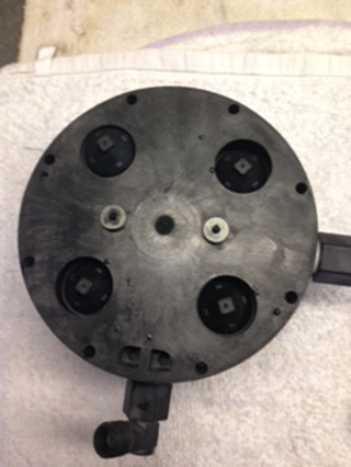
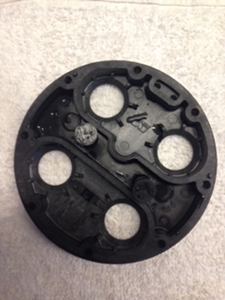
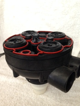
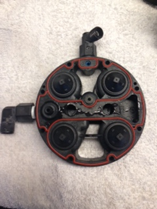
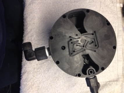
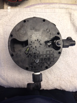
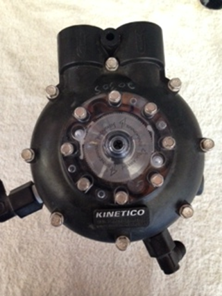
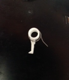
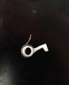
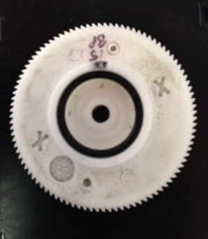
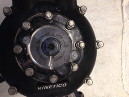
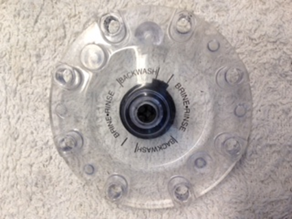
09.14.14 Here are the Kinetico Water Softener parts we carry. Have you ever heard the saying ‘A picture is worth 1,000 words’? Soon- more pictures of Kinetico Water Softener parts and services to arrive (all these will be posted) .
Kinetico water softener complete valve 1. Already been used (recycled) $200.00 plus tax
Kinetico water softener parts 2 ‘level 1’ part #211. Already been used (recycled) $5.00 plus tax.
Kinetico water softener parts 3. Already been used (recycled) $5.00 plus tax.
Kinetico water softener parts 4 ‘level 2/3’ part # 215. Already been used (recycled) $5.00 plus tax.
Kinetico water softener parts 5. Already been used (recycled) $5.00 plus tax.
Kinetico water softener parts 6. Already been used (recycled) $5.00 plus tax.
Kinetico water softener parts 7. Already been used (recycled) $5.00 plus tax.
Kinetico water softener parts 8. Already been used (recycled) $5.00 plus tax.
Kinetico water softener parts 9. Already been used (recycled) $5.00 plus tax.
Kinetico water softener parts 10. Already been used (recycled) $5.00 plus tax.
Kinetico water softener parts 11 . Already been used (recycled) $5.00 plus tax.
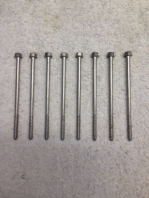
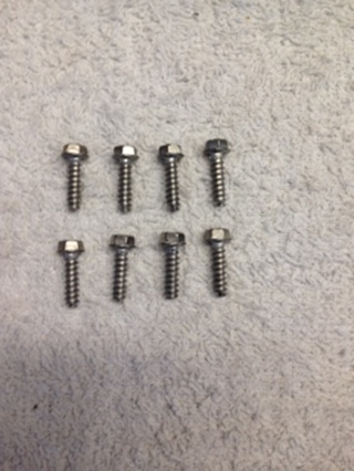
Kinetico water softener parts 12 ‘valve screws’ part # 210. Already been used (recycled) $5.00 plus tax.
Kinetico water softener parts 13. Already been used (recycled) $5.00 plus tax.
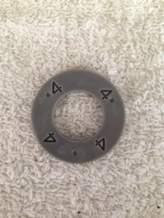
Kinetico water softener parts 14 ‘disc’ part # 238. Already been used (recycled) $5.00 plus tax.
Kinetico water softener parts 15 (screw ‘cap’ part # 236). Already been used (recycled) 50 cents plus tax.
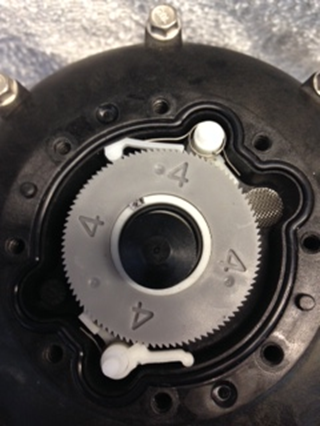
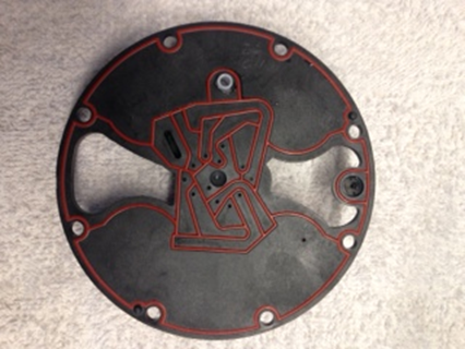
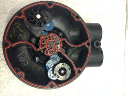
Kinetico water softener diagram 16. To show the assembly of these parts.
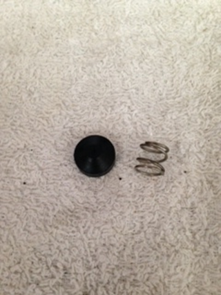
Kinetico water softener parts 17 ‘spring-piston’ part #249. Already been used (recycled) $1.00 plus tax.
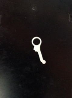
Kinetico water softener parts 18. Already been used (recycled) 50 cents plus tax.
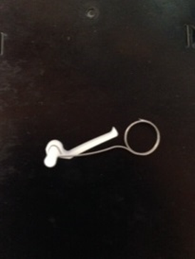
Kinetico water softener parts 19. Already been used (recycled) 50 cents plus tax.
Kinetico water softener parts 20. Already been used (recycled) 50 cents plus tax.
Kinetico water softener parts 21. Already been used (recycled) 50 cents plus tax.
Kinetico water softener parts 22. Already been used (recycled) $5.00 plus tax.
Kinetico water softener diagram 23. To show the assembly of these parts.
Kinetico water softener parts 24 ‘cap’ part # 237. Already been used (recycled) $5.00 plus tax.
08.08.14 Kinetico water softener. We have parts and perform service on this unit.
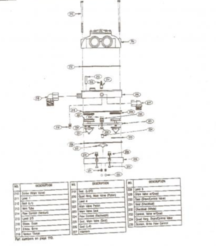
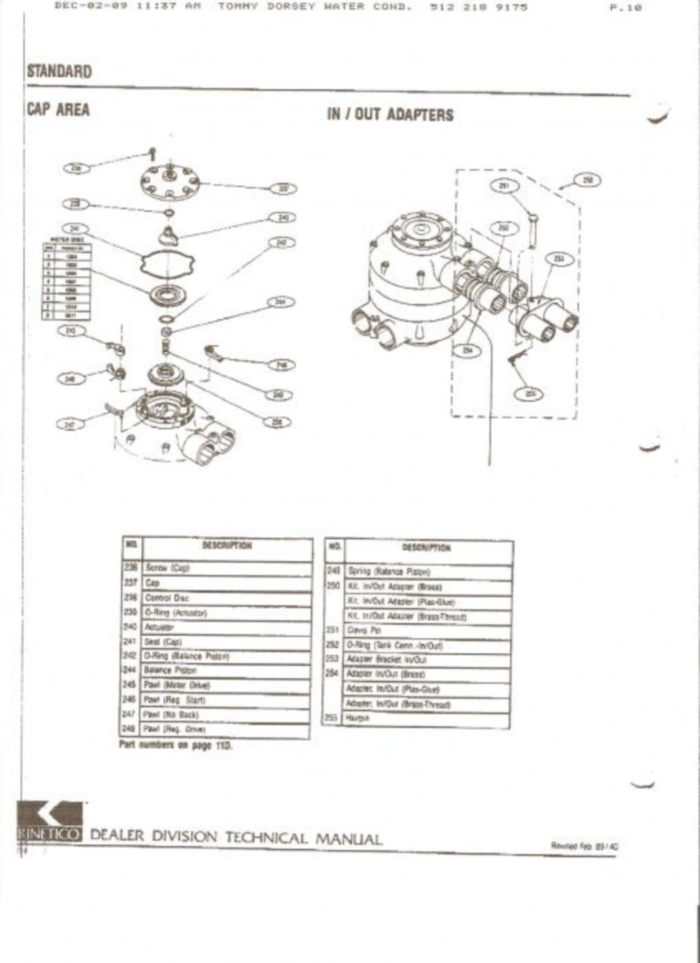
The above diagrams were taken from Google images; I typed in Kinetico parts diagrams. Brian Hayden Boyett BS, CWS-VI, CI
08.28.14 We will begin posting Kinetico parts that we recycle. If you need a Kinetico part we plan to inventory them all. If you buy your Kinetico parts from our company; the savings will be enormous.
08.29.14 10 AM. When we have enough Kinetico parts and components in our inventory we will begin providing these Kinetico Water softeners (and eventually Kinetico reverse osmosis units) on a rental basis for $30/mo plus tax. We will also sell these recycled units. The recycled units we sell will be ‘like new’. The price saving will be tremendous. In my opinion the retail prices of Kinetico units and parts require a large investment of money. We feel our recycling work with Kinetico parts, tanks and components – including cation resin replacement (resin change out on Kinetico Water Softeners; to change cation resin on Kinetico Water Softeners) and carbon media replacement (carbon media change out on Kinetico Water Softeners; to change the carbon media in a Kinetico Water Softener) will save our Kinetico clients thousands of dollars. We also feel with our expert technicians we will provide a very exceptional level of service and outstanding and friendly customer service. Our technicians are very communicative and responsive.
It is my opinion that Kinetico Water Softeners do not have enough cation resin media to effectively soften the hard Arizona water. We feel the most appropriate resin capacity (used continuously) is 64,000 grains. As I understand the present Kinetico residential water softeners being offered in this valley are much less than 64,000 grains (using 64,000 grains continuously ‘at the same time’). Therefore, based upon the flow rates of our pipes and appliances (please see this link for scientific data: http://www.azh2o.com/index.php?option=com_content&view=article&id=100) and the ability of ‘cation resin’ to soften the water; Kinetico water softeners may not be the most effective solution for our hard Arizona water. I’m just saying. However, we will be happy to help you keep your small Kinetico water softeners running. Kinetico water softeners regenerate constantly and waste much water. Please ask about our zero water waste whole house water treatment solution (which includes whole house carbon filtration for the entire home). We will provide you 100% chlorine free water with this water treatment method.
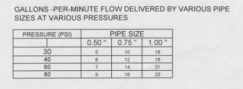
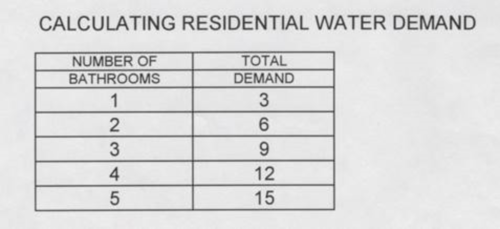
Source: the above two diagrams: ‘gallons – per – minute flow delivered by various pipe sizes at various pressures’ and ‘calculating residential water demand’ ( I found this information in my father’s file (William Brian Boyett ‘during his career he achieved the certification of CWS-V through the WQA.ORG’) titled Kinetico Water Softeners and Water Treatment equipment. He utilized this information when competing against the company known as Kinetico because their resin quantities are much smaller than ours and their units have a lower flow rate. For a single family home, or a business – both of these flaws can be a detriment when providing water treatment to an establishment.
This document was written and prepared by
Brian Hayden Boyett BS, CWS VI, CI
General Manager, Boyett’s Family Rayne Water Conditioning
Office: (480) 969-7251
Cell: (602) 291-4157
This email address is being protected from spambots. You need JavaScript enabled to view it.
This email address is being protected from spambots. You need JavaScript enabled to view it.
This email address is being protected from spambots. You need JavaScript enabled to view it.
This email address is being protected from spambots. You need JavaScript enabled to view it.
source: http://www.azh2o.com/index.php?option=com_content&view=article&id=100 (Theorigination date of this document is: 04.02.13)
#3
08.08.15 Erie water softener. We have parts available at our office (for this equipment). We are qualified to perform service on this unit.
#4
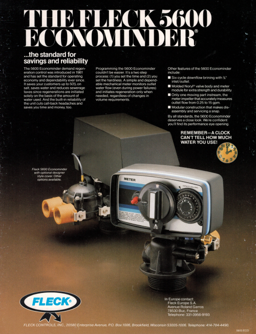
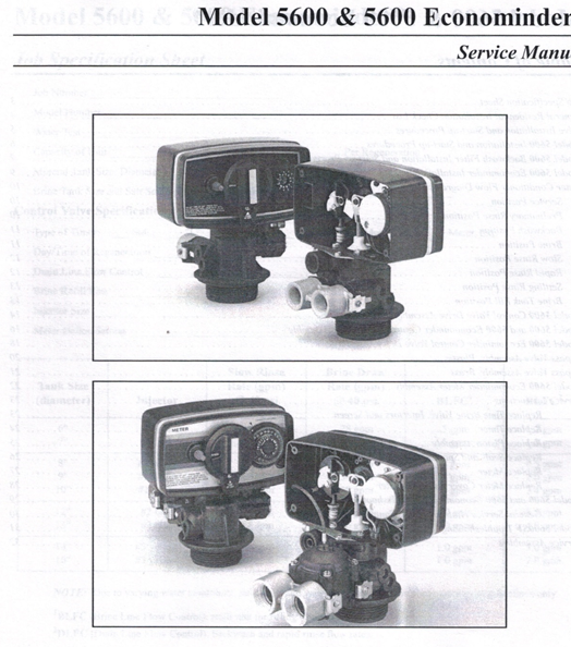
08.08.14 Fleck 5600 (Econominder) Water Softener. We have all the parts on this unit and are prepared to perform service on this unit.
This has been one of the most dependable valves in our industry. This is the valve that we utilize on most our residential rental water softeners.
This valve was developed in the 1980’s by a company called Fleck Controls. Fleck Controls used be called L.W. FLECKENSTEIN, INC. and people would say often they had a “Fleckenstein valve.” They are now called “Fleck Controls” and are owned by Pentair Water, a world conglomerate of water-related companies. Fleck makes a large number of control valves for residential and commercial water softeners and backwashing filters, and have been a world leader in this technology for over 50 years. (this is a extract from a Fleck Controls marketing media).
This is a marketing brochure describing our 5600 valve.
10.21.15 9:15 AM
Model 5600 & 5600 Fleck Econominder®
Service Manual
Model 5600 & 5600 Econominder®
Model 5600 Econominder Installation and Start-up Procedures
NOTE: Install the water softener with the inlet, outlet and drain connections made according to manufacturer’s recommendations and to meet applicable plumbing codes.
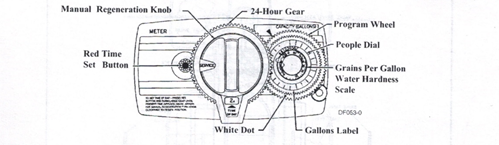
Manual Regeneration Knob 24-Hour Gear
Words in pictures:
Red Time Set Button
Manual Regeneration Knob
Program Wheel
24-Hour Gear
People Dial
White Dot
Grains Per Gallons Water Hardness Scale
Gallons Label
Model 5600 Econominder –
1Manually index the softener control to the In Service position and let water flow into the resin tank. When the water flow stops, open a softened water tap until all air is released from the lines. Then close tap.
NOTE: The various regeneration positions may be dialed manually by turning the knob on the front of the control until the indicator shows that the softener is in the desired position.
- Set water usage program wheel using anyone of the following procedures: Typical Residential Application
To program, just set the time, set the hardness and it automatically monitors system needs and regenerates only when necessary. To set time of day press red time set button and turn 24-hour gear until present time of day is at “time of day.” Set program wheel by lifting the “people” dial and rotating it so that the number of people in the household is aligned with the household grains per gallon water hardness. Release the dial and check for firm engagement at setting. This method provides reserve capacity based on 75 gallons per person.
– Optional Programming Procedures
Calculate the gallon capacity of the system, subtract the necessary reserve requirement and set the gallons available at the small white dot on program wheel gear. Note, drawing shows 850 gallon setting. The capacity (gallons) arrow denotes remaining gallons exclusive of fixed reserve.
- Rotate program wheel counterclockwise until it-stops at Regeneration position.
- Manually index the control to the Backwash position and allow water to flow at the drain for 3 or 4 minutes.
- Remove back cover plate.
- Make sure than the salt dosage is set as recommended by the manufacturer. Manually index the control to the Brine Fill position and allow the brine tank to fill to the top of the air check.
- Manually index the control to the Brine Rinse position and allow the control to draw water from the brine tank until it stops.
- Plug in the electrical cord and look in the sight hole in the back of the monitor to see that it is running.
- Manually advance the control to the beginning of the Brine Fill position and allow the control to return to the In Service position automatically.
- Fill the brine tank with salt.
- Replace back cover on the control. Be sure cable is not pinched between cover and housing.
- Make sure that any bypass valving is left in the normal In Service position.
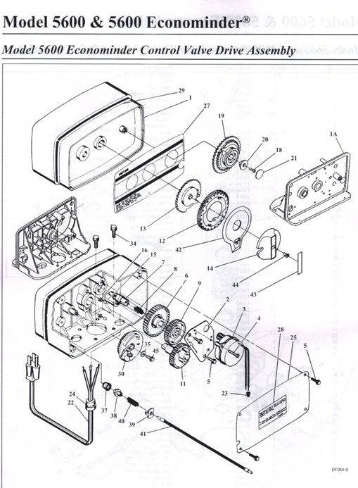
Model 5600 & 5600 Econominder®
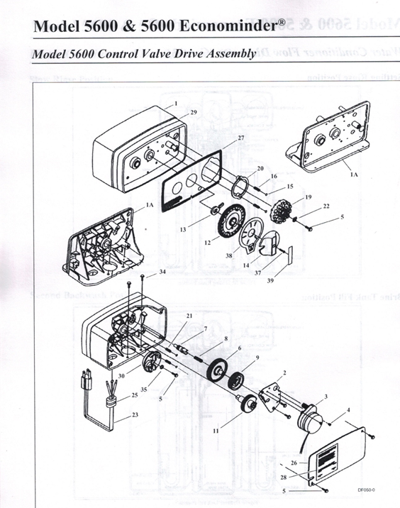
Model 5600 Control Valve Drive Assembly
Item Number No. Req ‘d Part Number Description
1 14448-010 housing, with pin
1 14448-011 housing, with pin drilled for screw
14448-012 housing, with pin drilled for thumb screw
IA 1 15494-01 “L” housing, with pin
15494-03 “L” housing, with pin drilled for designer
2 1 13175 motor mounting plate
3 1 18743 motor, 120V, 60 Hz
1 19659 motor, 24V 60 Hz
4 (2-3) 11384 screw, motor mtg. and ground wire
5 (3-5) 13296 screw, component mounting
6 1 13017 idler gear
7 1 13018 idler pinion
8 1 13312 spring, idler
9 1 13164 drive gear
11 1 13170 main gear and shaft
12 1 19205 24-hour gear assembly, silver
1 19205-01 24-hour gear assembly, tan
13 1 13011 cycle actuator gear
14 1 14177 knob, manual regeneration
15 4 13300 ball, 1/4″ dia.
16 2 13311 spring, detent, skipper wheel
19 1 14381 skipper wheel assembly, 12-day
1 14860 skipper wheel assembly, 7-day
20 1 13864 skipper wheel ring
21 2 14457 spring, detent, main gear
22 1 13014 regeneration pointer
23 1 11842 electrical cord, standard
24 2 12681 wire connector (not shown)
25 1 13547 strain relief
26 1 13229 back cover
27 1 13309 front label, brown on beige
1 13437 front label, blue/silver on black
28 1 13310 rear label, softener
1 18520 rear label, filter
29 1 13348 tape stripe, brown on beige
1 13436 tape stripe, blue on silver
30A 1 60514 brine cam assembly, 3-18
1 60514-01 brine cam assembly, 6-36
1 60514-02 brine cam assembly, minutes
34 2 12473 screw-drive mounting
35A 1 12037 washer
37 1 15151 screw, knob
38 1 14176 valve position dial, standard
1 14278 valve position dial, low water
1 15478 valve position dial, chemical filter
1 16715 valve position dial, filter
39 1 14175 knob label, beige
14207 knob label, silver
40A 1 40214 screw, brine cam
A Not used when a filter valve
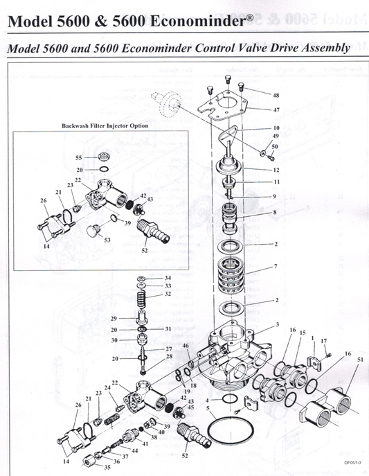
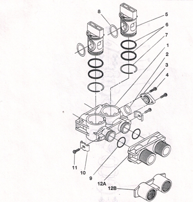
Model 5600 & 5600 Econominder®
Model 5600 and 5600 Econominder Control Valve Drive Assembly
Item Number No. Req’d Part Number Description
2-4 13255 adapter clip (clock or meter)
2 5 13242 seal
S 17772 silicone seal
3 I 61400-12 valve body assembly, l”dist.
61400-11 valve body assembly, 3/4″ dist.
4 1 13304 o-ring, distributor tube, I”
10244 o-ring, distributor tube, 13/16″
5 1 12281 o-ring, top of tank
6 6 not assigned
7 4 14241 spacer
8 1 13247 piston, standard
1 13781 piston, low water
1 13852 piston, filter
9 1 10696 piston pin
10 1 13001 piston rod assembly
II 1 12953 piston retainer
12 1 13446 end plug assembly standard, white
13446-10 end plug assembly filter, black
13 1 13446-20 end plug assembly low water, gray
14 2 13315 screw, injector mounting
15 2 19228 adapter coupling
16* 4 13305 o-ring, adapter coupling
I7 2-4 13314 screw, adapter coupling (clock or meter)
18 1 • 12638 o-ring, drain
19 2 13301 o-ring, injector
20A 2 13302 0-ring, brine spacer
21 1 13303 0-ring, injector cover
22 1 13163 injector body
23A I 10913U injector nozzle, undrillcd
24 1 10914 injector throat, specify size
25 1 10227 injector screen
26 1 13166 injector cover
27 1 13172 brine valve stem
28 1 12626 brine valve seat
29 1 13165 brine valve cap
30 I 13167 brine valve spacer
31 1 12550 quad ring
32 1 11973 spring, brine valve
33 1 16098 washer, brine valve
34 1 11981-01 retaining ring
35 1 10329 BLFC fitting nut
36 1 10330 BLFC ferrule
37 1 10332 BLFC tube insert
38 1 12094 BLFC button, .25gpm
12095 BLFC button, .50 gpm
1 12097 BLFC button, 1.0gpm
39A 1 12977 ring, BLFC
40 1 13245 BLFC button retainer
41 1 13244 BLFC fitting, 3/8″
42 1 DLFC button, specify size
43 1 13173 DLFC button retainer
44 1 12767 screen, brine line
45 1 15348 o-ring, DLFC (not shown)
46 1 13497 air disperser
47 I 13546 end plug retainer
48 3 12112 screw
49 1 13363 washer
50 1 13296 screw
51A 1 13398 yoke, brass, I” NPT
1 13708 yoke, brass, 3/4″NPT
SIB 1 18706 yoke, plastic, I” NPT
1 18706-02 yoke, plastic 3/4″ NPT
52 I 13308 drain hose barb
53 1 13918 BLFC. plug
54A 1 13857 brine valve, plug
* not used with meter controls A used in backwash filter
Model 5600 & 5600 Econominder®
Model 5600 Econominder Control Valve Drive Assembly
Item Number No. Req ‘d Part Number Description
1 14448-000 housing, with roll pin
14488-001 housing, with pin drilled for screw
14448-0 housing, with pin drilled for thumb screw
IA 1 15494-01 ‘L” housing, with pin
15494-03 “L” housing, with pin drilled for designer
2 1 13175 motor mounting plate
3 1 18743 motor, 120V 60 Hz
1 13494 motor, 24V 60 Hz
4 2-3 11384 screw, motor mtg. and ground wire
5 2-4 13296 screw, component mounting
6 1 13017 idler gear
7 1 13018 idlerpinion
8 1 13312 spring, idler
9 1 13164 drive gear
11 1 13170 main gear and shaft
12 1 19205 24-hour gear assembly, silver
1 19205-01 24-hour gear assembly, tan
13 1 13802 cycle actuator gear
14 1 14177 knob, manual regeneration
15 2 13300 ball, 1/4″ dia.
16 2 14457 spring, detent
18 I 13748 screw, program wheel
19 1 60405-I5 program skipper wheel assembly, specify hardness capacity
20 1 13806 program wheel retainer
21 1 13953 cover label, program wheel
22 1 11842 –
23 2 12681 wire connector
24 1 13547 strain relief
25 1 13229 back cover
26 not assigned
27 1 13955 front label, beige
13958 front label, silver
28 1 13310 rear label, softener
18520 rear label, filter
29 1 13957 tape stripe, beige
13960 tape stripe, silver
30 1 60514 brine cam assembly, 3-18
60514-01 brine cam assembly, 6-36
1 60514-02 brine cam assembly, minutes
34 2 12473 screw-drive mounting
35 I 12037 washer
37 1 13830 drive pinion, program wheel
38 1 13831 clutch, drive pinion
39 1 14253 spring retainer
40 1 14276 spring
41 1 14043 cable assembly, standard
14910 cable assembly, extended, right angle
42 1 14176 valve position dial, standard
14278 valve position dial, low water
I 15478 valve position dial, filter
43 1 14175 knob label, beige
I 14207 knob label, silver
44 1 15151 screw, knob
45 1 40214 screw, brine cam
MODEL 5600 & 5600 ECONOMINDER
by-pass valve assembly, plastic
PARTS LIST
Parts for the Fleck 5600 (RF Series): By-Pass Valve Assembly (plastic)
ITEM NO. NO. REQ’D PART NO. DESCRIPTION
1 1 19723 By-Pass Valve Body, Plastic
2 1 11183 0 Ring, -015
3 1 19724 Cap, By-Pass
4 2 17512 Screw, Hex Washer Head, #6-24 x 3
5 2 17820 Plug, By-Pass
6 4 18661 O Ring, -218
7 2 18662 Retaining Ring
8 2 18660 0 Ring
9 2 13305 0 Ring, 119
10 2 13255 Clip, Mounting
11 2 13314 Screw, Hex Washer Head. 8-18 x5/8
12A 1 18706 Yoke, Plastic, 1″ NPT
18706-02 Yoke, Plastic, 3/4″ NPT
12B 1 13708 Yoke, 3/4″
1 18708NP Yoke, 3/4″ Nickel Plated
1 13398 Yoke, 1″
1 13398NP Yoke, 1″ Nickel Plated
Model 5600 & 5600 Econominder®
Bypass Valve Assembly, Brass
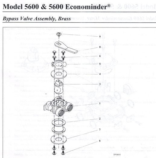
Here is some information regarding the 5600 bypass valve and components. We have all the parts and supplies to fix this bypass valve.
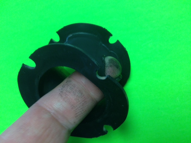
This is the part called the bypass boot.
This is my finger sticking through the hole.
This hole is caused by age and the chlorine (which the city puts in the water) breaks down the plastic.
There should be no hole.
The degradation of this part will cause the bypass valve to erroneously begin to leak.
If this happens – this may happen to you:

In our opinion; it is better to be proactive.
This part is inserted in this old 5600 bypass valve:
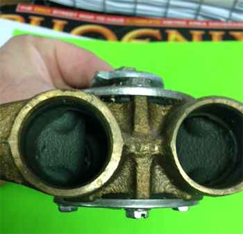
We sell the bypass boot for $15.00 plus tax. Please call to confirm we have this in stock.
Our office phone number is (480) 969-7251. Our address is: 38 East 5th Avenue, Mesa AZ 85210
Bypass Valve Assembly, Brass
Item Number No. Req ‘d Part Number Description
1 1 17290 bypass valve body, 3/4″
1 17290NP bypass valve body, 3/4″)
1 13399 bypass valve body, 1″
1 3399NP bypass valve body, 1″ (nickel-plated)
2 1 11726 seal, bypass
3 1 11972 plug, bypass
4 1 11978 side cover
5 1 13604-01 label
6 8 15727 screw
7 1 11986 side cover
8 1 11979 lever, bypass
9 1 11989 screw, hex head, 1/4-14
A good idea is to upgrade to this bypass valve. The flow rate is better and it comes with our Boyett’s Family Resin screen ‘world-wide invention’. No other water company offers this feature (The Boyett’s Family Resin screen). This is an image of the new bypass valve ‘with the Boyett’s Family Resin screen’:
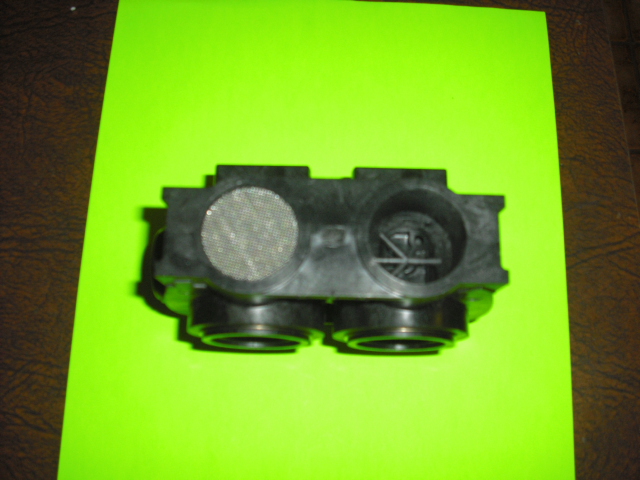
The screen will help prevent significant plumbing problems and financial loss by protecting your home – if the lower collector breaks.
This new bypass valve is more dependable and has a better flow rate.
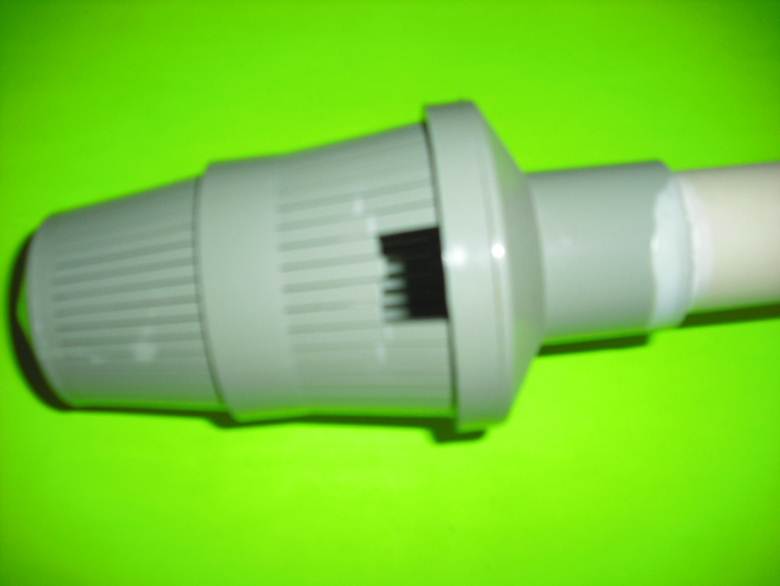
This is an image of a lower collector which has broken:
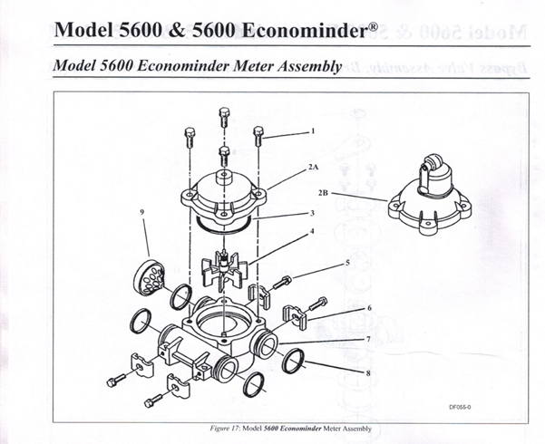
Model 5600 Econominder Meter Assembly
Item Number No. Req ‘d Part Number Description
1 4 12473 screw, meter cover assembly
2A 1 14038 meter cover assembly, standard
213 1 15659 meter cover assembly, extended range (right angle)
3 1 13847 0-ring, meter cover assembly
4 1 13509 impeller
5 4 13314 screw, adapter clip
6 4 13255 adapter clip
7 1 13821 meter body
8 4 13305 0-ring, meter body
9 1 14613 flow straightener
This 5600 water softener (in Mesa, AZ; Chandler, AZ; Phoenix, Arizona; Cave Creek, AZ) is also known as an Ultima Water softener – distributed by a famous water treatment manufacture named B and R Industries (BR Industries, B and R Water softeners and RO units Mesa, Arizona, Phoenix, Arizona, Glendale, Arizona).
Model 5600 & 5600 Econominder®
Service Instructions
Replace Time Brine Valve, Injectors and Screen
- Unplug electrical cord from outlet.
- Turn off water supply to conditioner:
If the conditioner installation has a “three valve” bypass system, first open the valve in the bypass line, then close the valves at the conditioner inlet and outlet.
If the conditioner has an integral bypass valve, put it in the Bypass position. If there is only a shut-off valve near the conditioner inlet, close it.
- Relieve water pressure in the conditioner by putting the control in the Backwash position momentarily. Return the control to the In Service position.
- Disconnect brine tube and drain line connections at the injector body.
- Remove the two injector body mounting screws. The injector and brine module can now be removed from the control valve. Remove and discard valve body o-rings.
- Replace brine valve.
Pull brine valve from injector body, also remove and discard o-ring at bottom of brine valve hole. Apply silicone lubricant to new o-ring and reinstall at bottom of brine valve hole.
Apply silicone lubricant to o-ring on new valve assembly and press into brine valve hole, shoulder on bushing should be flush with injector body.
- Replace injectors and screen.
Remove injector cap and screen, discard o-ring. Unscrew injector nozzle and throat from injector body. Screw in new injector throat and nozzle, be sure they are seated tightly. Install a new screen.
Apply silicone lubricant to new o-ring and install around oval extension on injector cap.
- Apply silicone lubricant to three new o-rings and install over three bosses on injector body.
- Insert screws with washers through injector cap and injector. Place this assembly through hole in timer housing and into mating holes in the valve body. Tighten screws. (Be sure to reinstall brass spacers with injector on model 4600 valve.)
- Reconnect brine tube and drain line.
- Return bypass or inlet valving to normal In Service position. Water pressure automatically builds in the conditioner. NOTE: Be sure to shut off any bypass line.
- Check for leaks at all seal areas. Check drain seal with the control in the Backwash position.
- Plug electrical cord into outlet.
- Set time of day and cycle the control valve manually to assure proper function.
— Make sure control valve is in the In Service position.
- Make sure there is enough brine in the brine tank.
- Rotate program wheel counterclockwise until it stops at Regeneration position.
- Start regeneration cycle manually if water is hard.
Model 5600 & 5600 Econominder®
Service Instructions (Contd.)
Replace Timer
- Unplug electrical cord from outlet.
- Turn off water supply to conditioner:
– If the conditioner installation has a “three valve” bypass system, first open the valve in the bypass line, then close the. valves at the conditioner inlet and outlet.
– If the conditioner has an integral bypass valve, put it in the Bypass position. If there is only a shut-off valve near the conditioner inlet, close it.
- Relieve water pressure in the conditioner by putting the control in the Backwash position momentarily. Return the control to the In Service position.
- Pull cable out of meter cover. Remove the control valve back cover.
- Remove screw and washer at drive yoke. Remove timer mounting screws. The entire timer assembly now lifts off easily.
- Put new timer on top of valve. Be sure drive pin on main gear engages slot in drive yoke (rotate control knob if necessary).
- Replace timer mounting screws. Replace screw and washer at drive yoke.
- Return bypass or inlet valying to normal In Service position. Water pressure automatically builds in the conditioner. NOTE: Be sure to shut off any bypass line.
- Plug electrical cord into outlet.
- Set time of day, program wheel, and salt usage. Cycle the control valve manually to assure proper function. Be sure to return the control valve to the In Service position.
- Replace the control valve back cover. Be sure grommet at cable hole is in place.
- Make sure there is enough brine in the brine tank.
- Rotate program wheel counterclockwise until it stops at Regeneration position.
- Start regeneration cycle manually if water is hard.
- Plug cable into meter cover, rotate cable to align drive flat if necessary.
Model 5600 & 5600 Econominder®
Service Instructions (Contd.)
Replace Piston Assembly
- Unplug electrical cord from outlet.
- Turn off water supply to conditioner:
If the conditioner installation has a “three valve” bypass system, first open the valve in the bypass line, then close the valves at the conditioner inlet and outlet.
If the conditioner has an integral bypass valve, put it in the Bypass position. – If there is only a shut-off valve near the conditioner inlet, close it.
- Relieve water pressure in the conditioner by putting the control in the Backwash position momentarily. Return the control to the In Service position.
- Pull cable out of meter cover. Remove the control valve back cover.
- Remove screw and washer at drive yoke. Remove timer mounting screws. The entire timer assembly now lifts off easily. Remove end plug retainer plate.
- Pull upward on end of piston yoke until assembly is out of valve.
- Inspect the inside of the valve to make sure that all spacers and seals are in place, and that there is no foreign matter that would interfere with the valve operation.
- Take new piston assembly as furnished and push piston into valve by means of the end plug. Twist yoke carefully in a clockwise direction to properly align it with drive gear. Replace end plug retainer plate.
- Place timer on top of valve. Be sure drive pin on main gear engages slot in drive yoke (rotate control knob if necessary).
- Replace timer mounting screws. Replace screw and washer at drive yoke.
- Return bypass or inlet valving to normal In Service position. Water pressure automatically builds in the conditioner. NOTE: Be sure to shut off any bypass line.
- Plug electrical cord into outlet.
- Set time of day, program wheel, and salt usage. Cycle the control valve manually to assure proper function. Be sure to return the control valve to the In Service position.
- Replace the control valve back cover. Be sure grommet at cable hole is in place.
- Make sure there is enough brine in the brine tank.
- Rotate program wheel counterclockwise until it stops at Regeneration position.
- Start regeneration cycle manually if water is hard.
- Plug cable into meter cover. Rotate cable to align drive flat if necessary.
Model 5600 & 5600 Econominder®
Service Instructions (Contd.)
Replace Seals and Spacers
- Unplug electrical cord from outlet.
- Turn off water supply to conditioner:
If the conditioner installation has a “three valve” bypass system, first open the valve in the bypass line, then close the valves at the conditioner inlet and outlet.
– If the conditioner has an integral bypass valve, put it in the Bypass position. – If there as only a shut-off valve near the conditioner inlet, close it.
- Relieve water pressure in the conditioner by putting the control in the Backwash position momentarily. Return the control to the In Service position.
- Pull cable out of meter cover. Remove the control valve back cover.
- Remove screw and washer at drive yoke. Remove timer mounting screws. The entire timer assembly now lifts off easily. Remove end plug retainer plate.
- Pull upward on end of piston rod yoke until assembly is out of valve. Remove and replace seats and spacers with fingers.
Model 5600 & 5600 Econominder®
Service Instructions (Contd.)
Replace Meter
- Unplug electrical cord from outlet.
- Turn off water supply to conditioner:
If the conditioner installation has a “three valve” bypass system, first open the valve in the bypass line, then close the
valves at the conditioner inlet and outlet.
If the conditioner has an integral bypass valve, put it in the Bypass position.
If there is only a shut-off valve near the conditioner inlet, close it.
- Relieve water pressure in the conditioner by putting the control in the Backwash position momentarily. Return the control
to the In Service position.
- Pull cable out of meter cover.
- Remove two screws and clips at bypass valve or yoke. Pull resin tank away from plumbing Connections.
- Remove two screws and clips at control valve. Pull meter module out of control valve.
- Apply silicone lubricant to four new 0-rings and assemble to four ports on new meter module.
- Assemble meter to control valve.Note, meter portion of module must be assembled at valve outlet.
- Attach two clips and screws at control valve. Be sure clip legs are firmly engaged with lugs.
- Push resin tank back to the plumbing connections and engage meter ports with bypass valve or yoke.
- Attach two clips and screws at bypass valve or yoke. Be sure clip legs are firmly engaged with lugs.
- Return bypass or inlet valving to normal In Service position. Water pressure automatically builds in the conditioner. NOTE: Be sure to shut off any bypass line.
- Check for leaks at all seal areas.
- Plug electrical cord into outlet.
- Set time of day.
– Make sure control valve is in the In Service position.
- Rotate program wheel counterclockwise until it stops at Regeneration position.
- Start regeneration cycle manually if water is hard.
- Plug cable into meter cover. Rotate cable to align drive flat if necessary.
Model 5600 & 5600 Econominder®
Service Instructions (Contd.)
Replace Meter Cover and/or Impeller
- Unplug electrical cord from outlet.
- Turn off water supply to conditioner:
If the conditioner installation has a “three valve” bypass system, first open the valve in the bypass line, then close the valves at the conditioner inlet and outlet.
– If the conditioner has an integral bypass valve, put it in the Bypass position If there is only a shut-off valve near the conditioner inlet, close it.
- Relieve water pressure in the conditioner by putting the control in the Backwash position momentarily. Return the control to the In Service position.
- Pull cable out of meter cover.
- Remove four screws on cover
- Lift cover off of meter module, discard o-ring.
- Remove and inspect impeller for gear or spindle damage, replace if necessary.
- Apply silicone lubricant to new 0-ring and assemble to the smallest diameter on meter cover.
- Assemble cover to meter module. Be sure impeller spindle enters freely into cover. Press firmly on cover and rotate if necessary to assist in assembly.
- Replace four screws and tighten.
- Return bypass or inlet valving to normal In Service position. Water pressure automatically builds in the conditioner. NOTE: Be sure to shut off any bypass line.
- Check for leaks at all seal areas.
- Plug electrical cord into outlet.
- Set time of day.
Make sure control valve is in the In Service position.
- Rotate program wheel counterclockwise until it stops at Regeneration position.
- Start regeneration cycle manually if water is hard.
- Plug cable into meter cover. Rotate cable to align drive flat if necessary.
Model 5600 & 5600 Econominder®
Model 5600 and 5600 Econominder Troubleshooting
PROBLEM CAUSE CORRECTION
1.Softener fails to regenerate. A.Electrical service to unit has been A.Assure
interrupted. permanent electrical
service
(check fuse, plug, pull chain
or
switch).
B.Timer is defective. B. Replace timer.
- Power failure. C.Reset time of day.
2.Softener delivers hard water. A.Bypass valve is open. A.Close bypass valve.
B.No salt in brine tank. B. Add salt to brine tank and
Maintain salt level above
water level.
- Injectors or screen is plugged. C.Replace injectors and
screen.
D.Insufficient water flowing into brine tank. D.Check brine tank fill time
and clean
brine line flow control if plugged.
E.Hard water tank hardness. E.Repeated flushings of the
hot water
tank is required.
F.Leak at distributor tube. F.Make sure distributor tube is
Not cracked. Check 0-ring and
tube pilot.
G.Internal valve leak. G.Replace seals and spacers and/or
piston.
3.Unit uses too much salt. A.Improper salt setting. A.Check salt usage and salt setting.
B.Excess water in brine tank. B.See problem number 7.
4.Loss of water pressure A.Iron build-up in line to water conditioner. A.Clean line to water
conditioner.
B.Iron build-up in water conditioner. B.Clean control and add resin
cleaner to
resin bed. Increase frequency of
regeneration.
- Inlet of control plugged due to foreign C.Remove piston and clean
material loose from pipes by recent work control.
done on plumbing system.
5.Loss of resin through drain line. A.Air in water system. A.Assure that well system has
proper air elimination control,
check for dry well condition.
6.Iron in conditioned water. A.Fouled resin bed. A.Check backwash, brine draw and
brine tank fill, increase frequency of
regeneration, increase backwash
time.
7.Excessive water in brine tank. A.Plugged drain line flow control. A.Clean flow control.
8.Salt water in service line. A.Plugged injector system. A.Clean injector and replace screen.
B.Timer not cycling. B. Replace timer.
- Foreign material in brine valve. C.Clean or replace brine valve.
D.Foreign material in brine line flow control. D.Clean brine line flow
control.
Model 5600 & 5600 Econominder®
Model 5600 and 5600 Econominder Troubleshooting (Contd.)
PROBLEM CAUSE CORRECTION
9.Softener fails to draw brine. A.Draw line flow control is plugged. A.Clean drain line
flow control.
B.Injector is plugged. B.Clean or replace injectors.
C.Injector screen plugged. C.Replace screen.
D.Line pressure is too low. D. Increase line pressure
(minimum 20
psi at all times).
- Internal control leak. E.Change seals, spacers
and/or piston
assembly.
- Control cycles continuously. A.Faulty timer mechanism. A.Replace timer.
11.Drain flows continuously. A.Foreign material in control. A.Remove piston assembly
and inspect
bore, remove foreign
material and
check control in various
regeneration positions.
B.Internal control leak. B. Replace seals and/or
piston assembly.
- Control valve jammed in Brine or C.Replace seals and/or piston
Backwash position. assembly.
D.Timer motor stopped or jammed. D.Replace timer.
General Service Hints for Meter Control
PROBLEM CAUSE CORRECTION
Softener delivers hard water. A.Reserve capacity has been exceeded. A.Check salt dosage
requirements and
reset program wheel to
provide
additional reserve.
B.Program wheel is not rotating with meter B.Pull cable out of
output. meter cover and
rotate manually, program
wheel must move without
binding and clutch must give
positive “clicks”
when program wheel strikes
regeneration stop (if not, replace
timer).
C.Meter is not measuring flow. C.Check output by observing
rotation
of small gear on front of timer
(program wheel must not be against
regeneration stop for this check)
each tooth to tooth is approximately
30 gallons (if not, replace meter).
Model 5600 & 5600 Econominder®
Model 5600SF Troubleshooting
PROBLEM CAUSE CORRECTION
1.Filter fails to backwash. A.Electrical service to unit has been A.Assure permanent
interrupted. electrical service
(check fuse, plug, pull chain or
switch).
B.Timer is defective. B. Replace timer.
- Power failure. C.Reset time of day.
2.Filter “bleeds” iron. A.Bypass valve is open. A.Close bypass valve.
B.Excessive water usage. B. Reduce days between,
backwashing
(see timer instructions), make sure
that there is not a leaking valve in the
toilet bowl or sinks.
- Hot water tank rusty. C.Repeated flushings of the
hot water tank is required.
D.Leak at distributor tube. D.Make sure distributor tube
is not cracked, check 0-ring
and tube pilot.
E.Defective or stripped filter medium bed. E.Replace bed.
F.Inadequate backwash flow rate. F.Make sure filter has
correct drain
flow control, be sure flow control
is not clogged or drain
line restricted, be sure water
pressure has not dropped, increase
backwash flow rate according to
specifications for your
unit, see your dealer for
recommendations.
- Loss of water pressure. A.Iron or turbidity build-up in water filter. Reduce days
between backwashing
so filter backwashes more often,
make sure filter is sized large enough
to handle water usage.
B.Inlet plugged due to foreign material B.Remove piston and clean control.
broken loose from pipes by recent work
done on plumbing system.
4.Loss of filter medium through A.Broken or missing top screen. A.Replace top screen, must
have 0.020″ drain line, wide slots.
5.Drain flows continuously. A.Foreign material in control. A.Remove piston assembly and
Inspect bore, remove foreign
material and
check control in various cycle
positions.
B.Internal control leak. B. Replace seals and/or piston
assembly.
- Control valve jammed in rinse or C.Replace piston, seals and
spacers
backwash. (and drive motor if necessary).
Model 5600 & 5600 Econominder®
Service Assemblies
Part Number Description
60102-00 piston, softener
60102-10 piston, filter
60102-20 piston, low water
60125 seal kit
60084-XX injector
60032 brine valve
60514 brine cam, 3-18
60514-01 brine cam, 6-36
60514-02 brine cam, minutes
60510 coupling, with clip and screws
60040 bypass, brass 3/4″ NPT
60041 bypass, brass 1″ NPT
60049 bypass, plastic
60086 meter, standard
60087 meter, extended
160136-5600 service kit, meter
160135-5600 service kit, clock
14860 skipper wheel, 7-day
14381 skipper wheel, 12-day
60405-10 meter program wheel, standard
60405-20 meter program wheel, extended
Parts for the Fleck 5600 Fleck (Rayne RF Series): Complete assemblies
PART NO. DESCRIPTION
60022-50 BRINE LINE FLOW ASSEMBLY
60032 BRINE VALVE
61020 BRINE VALVE ASSEMBLY (SHURZ)
60040 3/4″ BYPASS VALVE
60041 1″ BYPASS VALVE
60084 INJECTOR/ DRAIN MODULE
60086 METER MODULE COMPLETE
14038 METER COVER ASSEMBLY
60102-00 PISTON ASSEMBLY (STANDARD)
60102-20 PISTON ASSEMBLY (LOW FLOW)
60125 SEAL KITS
60514 BRINE CAM ASSEMBLY
60354-00 POWER HEAD METER
60353-00 POWER HEAD T/C
COMPLETE VALVE AND POWER HEAD
METER NO B.P.
COMPLETE VALVE AND POWER HEAD T/C
NO B.P.
13708 3/4″ BOSS ADAPTER
13398 1″ BOSS ADAPTER
13400 110 VOLT MOTOR
13494 24 VOLT MOTOR
13170 MAIN GEAR AND SHAFT
13168 BRINE CAM
14043 METER CABLE
13830 DRIVE PINION
13831 CLUTCH PINION
14253 SPRING RETAINER
14276 SPRING
11726 BY-PASS BOOT
60225-01 DUST COVER FOR TIMER (STANDARD)
60226-11 COVER FOR L STYLE TIMER
61400-12 VALVE BODY ONLY – 1″ DISTRIBUTOR
61400-11 VALVE BODY ONLY – 3/4″ DISTRIBUTOR
5600 OWNERS SERVICE MANUAL
Fleck 5600 Valve ( and Rayne RF Series)
This 5600 valve is so dependable we refer to this valve performance as bullet proof. Because of this dependability we utilize this valve on most of our rental water softeners.
This is an image of cation resin beads taken under a microscope.
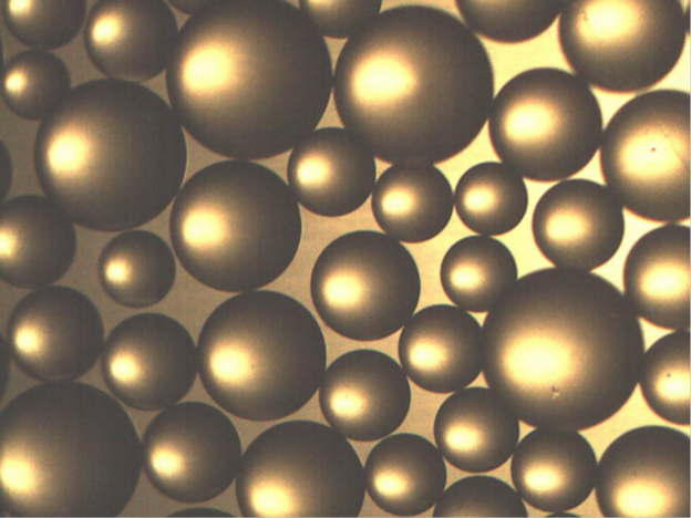
We recently sent a sample of cation resin (water softener media) to a laboratory for testing purposes. This is a description of the test performed.
MICROSCOPIC BEAD EXAMINATION:
A sample of the resin is placed under the microscope for determination of the physical integrity of the resin and contamination of the bead.
#5
08.08.15 Fleck 5000SE. We have all the parts necessary to rebuild this unit (including the cation resin). We also carry the turbines (these are prone to fail in Arizona ‘because of the corrosive water’).
09.02.14 A common problem we are finding, on this unit, is that it is not reading the gallons (the gallons do not count down). This can cause hard water. The solution; replace the turbine. These turbines are problematic and need to replaced often.
Another problem we are experiencing with this type unit is error codes. If you ever receive an error code on this unit please call us (480) 969-7251 or e mail me This email address is being protected from spambots. You need JavaScript enabled to view it. and we will help you develop a solution to this problem.
10.28.15 1:45 PM
ProFloSE Downflow brining service manual water softener (fleck 5000SE water softener)
ProFloSE Downflow brining service manual water softener (fleck 5000SE water softener)
General Residential Installation Check List
WATER PRESSURE: A minimum of 20 psi inlet water pressure is required for regeneration valve to operate effectively
ELECTRICAL FACILITIES: An uninterrupted alternating current (A/C) supply is required. Please make sure your voltage supply is compatible with your unit before installation.
EXISTING PLUMBING: Condition of existing plumbing should be free from lime and iron buildup. Piping that is built up heavily with lime and/or iron should be replaced. If piping is clogged with iron, a separate iron filter unit should be installed ahead of the water softener.
LOCATION OF SOFTENER AND DRAIN: The softener should be located close to a clean working drain and connected according to local plumbing codes.
BY-PASS VALVES: Always provide for the installation of a by-pass valve if unit is not equipped with one.
CAUTION: Water pressure is not to exceed 120 p.s.i., water temperature is not to exceed 11000017, and the unit cannot be subjected to freezing conditions.
Valve Installation and Start-up Procedures
INSTALLATION INSTRUCTIONS
1 Place the softener tank where you want to install the unit making sure the tanks are level and on a firm base
- All plumbing should be done in accordance with local plumbing codes. The pipe size for the drain line should be a minimum of 1/2″. Backwash flow rates in excess of 7 gpm or length in excess of 20′ require 3/4″ drain line.
- The 1″ distributor tube (1.050 O.D.) should be cut flush with top of tank.
- Lubricate the distributor o-ring seal and tank o-ring seal. Place the main control valve on tank. Note: Only use silicone lubricant.
5 Solder joints near the drain must be done prior to connecting the Drain Line Flow Control fitting (DLFC) Leave at least 6″
between the DLFC and solder joints when soldering pipes that are connected on the DLFC Failure to do this could cause interior damage to the DLFC.
- Teflon tape is the only sealant to be used on the drain fitting.
- Make sure that the floor is clean beneath the salt storage tank and that it is level.
8 On units with a by-pass place in by-pass position Turn on the main water supply. Open a cold soft water tap nearby and let run a few minutes or until the system is free from foreign material (usually solder) that may have resulted from the installation. Once clean, close the water tap.
- Place the by-pass in service position and let water flow into the mineral tank. When water flow stops, slowly open a cold water tap nearby and let run until the air is purged from the unit.
- Plug unit into an electrical outlet. Note: All electrical connections must be connected according to local codes.
- Add water to the top of the air check. Manually step the valve to the Brine Draw Position and allow the valve to draw water from the brine tank until it stops. Note: The air check will check at approximately the midpoint of the screened intake area.
- Next, manually step the valve to the Brine Refill Position and allow the valve to return to Service automatically.
- With the valve in Service, check that there is about 1.0″ of water above the grid in the brine tank, if used.
- Fill the brine tank with salt.
- Set-Up is now finished, the control can now be left to run automatically.
U.S.A.
ProFloSE Downflow 5000SE
Valve Power head Assembly Parts List
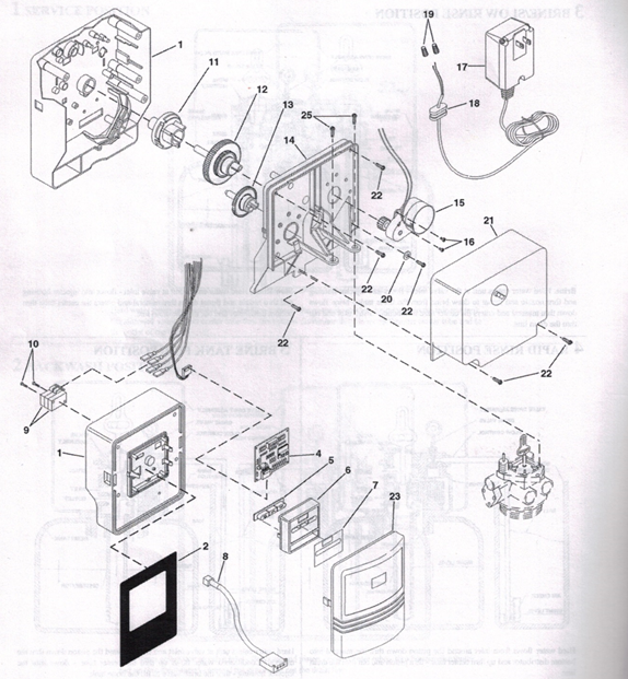
ProFloSE Downflow
Valve Power Assembly Parts List
Item No Quantity Part No Description
1………………………..1 ………….40269………………Plate, Front
2……………………….1 …………. 40326………………Label, Cover-up
3…………………………1 ………….19474………………Harness, Power
4………………………….1………….40283………………Circuit Board, SE Timer
5…………………………..1 ………….40376………………Button, Conductive
6……………………1 ………….19471-02 …………… Cover, Front Panel
7……………………1……………..19697-01 …………….Label, Display
8…………………..1 ………….19791-01 ……………Meter Cable Assy., Turbine
9……………………2 …………. 10218 ……………… Switch, Micro
10 ……………………2 …………. 17876 ………………. Screw #4-40×1.125
11…………………….1 ………….19927………………Cam, Switch Downflow
12 …………………..1 ………….18211-01 ……………Gear, Main Downflow
13 …………………1 …………… 18228 ……………… Cam, Brine, Downflow
14 ……………………..1 ………….18202-03 ……………Back Plate
15 ……………………..1 ………….40251………………Motor Assy., 24V 50/60Hz
16 …………………….2 …………. 13602 ……………… Screw, Rd. Hd. 6-33 x 5/16
17 …………………….1 ………….19674………………Transformer U.S. 24V (120V) 50/60HZ
1…………. 25651 ……………… Transformer European 24V (230V)
18 ……………………..1 ………….13547………………Strain Relief
19 …………………….4 …………. 12681 ……………… Nut, Wire, Beige
20 ……………………..1………….. 13363 ……………… Washer, Plain, .145 I.D.
21 ……………………….1 ………….18259-02 ……………Cover, Back Black
22 ……………………..6 …………. 13296 ……………… Screw, Hex Washer 6-20 x 1/2
23 ………………………..1………….18260-00 ……………Cover, Front Smoke
24 ………………………..2 ………….18261………………Screw,HexHead,10-24×13/16
Not Shown …………….1………….14044………………Cable Tie
U.S.A.
ProF1oSE Downflow water softener
Control Valve Assembly Parts List
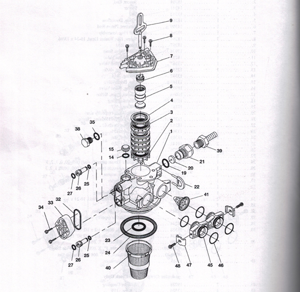
ProF1oSE Downflow water softener
Control Valve Assembly Parts List
Item No Quantity Part No Description
1……………………….1 ………….18815 …………. Valve Body, 5000, 1″ Dist.
2……………………….1 ………….18264 ………….Spacer, End
3………………………..4 ………….14241 ………….Spacer
4…………………………5 ………….13242 ………….Seal
5…………………………1 ………….18265 ………….Piston, Downflow
6……………………………1…………14309 ………….Retainer, Piston Rod
7………………………..1 ………….18268 …………..End Plug Assembly
8……………………….3 ………….18261 ………….Screw, Hex Washer Head, 10-24 x 13/16
9………………………..1 ………….18267 ………….Piston Rod
10………………………..1………….17978 ………….Brine Valve Stem
11………………………1 ………….18755 …………..Seat, Brine Valve
12………………………1 ………….13167 …………. Spacer, Brine Valve
13………………………1…………12550 ………….Quad Ring, -009
14………………………2 ………….13302 …………. ORing, -014
15……………………..1 ………….13165 …………..Cap,Brine Valve
16……………………….1………..11973 …………..Spring, Brine Valve
17………………………1…………16098 …………..Washer, Plain, Nylon
18……………………….1 …………. 11981-01 ……….. Retaining Ring
19…………………………….1…………11183 ………….0-Ring, -017
20…………………………..1 ………………………………Flow Washer (specify size)
21…………………………..1………….11385-01………..Flow Control Housing, Plastic
22…………………………….1………..18312 ………….Retainer, Drain
23………………………….1 ………….13304 ………….0-Ring, -121
24………………………….1 ………….18303 …………..0-Ring, -336
25………………………….2 ……………10141 ………….0-Ring, -010
26………………………….1 ………….18276 ………….Plug, Injector
27…………………………..2 ………….13771 …………. 0-Ring,-012
28…………………………..1………….18275-X ………..Injector Throat (specify size) 000, 00, 0, 1, 2, 3 29…………………………..1 ………….18274-X ………..Injector Nozzle (specify size) 000, 00, 0, 1, 2, 3 30…………………………….1 ………….18273 ………….Vortex Generator
31……………………………1…………18271 ………….Screen Injector
32……………………………1 ………….18301 ………….Seal, Injector
33………………………….1 ………….18277 . . . ……… Cap, Injector, Softener
34…………………………….2 ………….18262 …………..Screw, Hex Washer Head, 10-24 x 1
35……………………………1………….12977 …………..0-Ring, -015
36……………………………..1………….13245 ………….Retainer, BLFC Button
37…………………………….1 …………………………..Flow Washer (specify size)
38……………………………1………….13244 …………..Adapter, BLFC
39……………………………..1…………13308 ………….Hose Barb, Black, 1/2 x 1/2 Straight
………………………………….1 …………….12338 ………….Hose Barb, Black, 1/2 x 1/2 90° Elbow 40……………………………..1 ………….18280 ………….Top Collector, I”, X .011, Gray
…………………………………..1 ………….18280-01………..Top Collector, 1″, X.020 White, Wide Slot
………………………………….I …………..18280-02…………Top Collector, 1″, X .008 Red, Narrow Slot
41 ………………………………1 …………..14613 …………..Flow Straightener
OPTION
Adapter Coupling Day Clock Only
45…………………………………2 …………..19228 …………..Adapter Coupling
46………………………………….4 ………….13305 ………….0-Ring, -119
47…………………………………2 ………….13255 ………….Clip, Mounting
48………………………………….2 ………….13314 ………….Screw, Hex Washer Head 8-18 x 5/8
U.S.A.
ProFLoSE (5000SE FLECK) WATER SOFTENER
2310 Safety Brine Valve Parts List
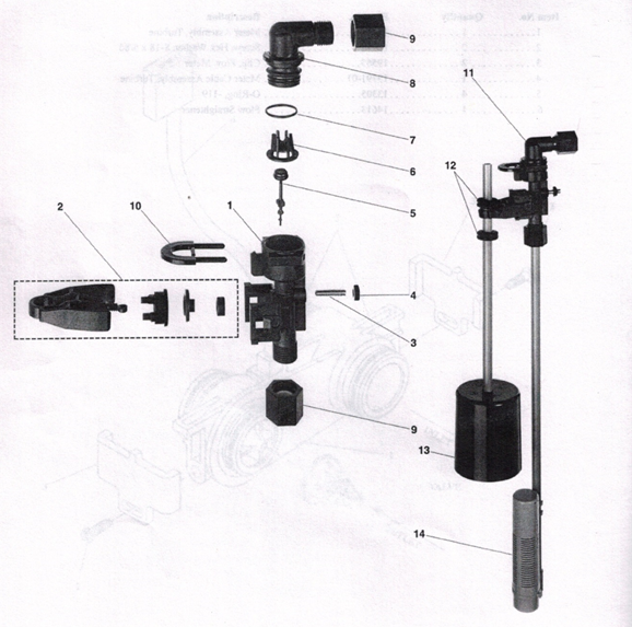
ProFLoSE (5000SE FLECK) WATER SOFTENER
2310 Safety Brine Valve Parts List
Item No. Quantity Part No Description
I………………………….1 …………. 19645 ……………… Safety Brine Valve Body
2…………………………..I …………..19803………………Safety Brine Valve Arm Assembly
3…………………………1 …………. 19804 ……………… Stud, 10-24
4…………………………1 ………….19805………………Nut, 10-24
5………………………….1 ………….19652-01 …………… Poppet & Seal
6…………………………….1 ………….19649………………Flow Dispenser
7……………………………..1 ………….11183 ………………0-Ring, -017
8……………………………..1 ………….19647………………Elbow, Safety Brine Valve
9…………………………….2 ………….19625………………Nut Assembly, 3/8
10 ………………………..1 ………….18312………………Retaining Clip
11…………………………1 ………….60014………………Safety Brine Valve, 2310 (includes items 1-10)
12 ………………………….2 ………….10150………………Grommet (included with item 13)
13 …………………………..1 …………. 60068 ……………… Float Assembly, 2310
14 …………………………..1 …………..60002………………500 Air Check Assembly
U.S.A.
ProF1oSE Downflow water softener (5000SE)
By-Pass Valve Assembly, Plastic Parts List

ProF1oSE Downflow water softener (5000SE)
By-Pass Valve Assembly, Plastic Parts List
Item No Quantity Part No Description
9 ………… 2 ………….13305 …………O-Ring,-119
10 ………… 2 ………….13255………………Clip, Mounting
11 …………2 ………….13314 ………………Screw, Hex Washer Head, 8-18×5/8
12A ………. I ………….18706………………Yoke, Plastic, 1″ NPF
18706-02 ……………Yoke, Plastic 3/4″
12B……….. 1 ………….13708 ………………Yoke, 314″
1 ………….13708NP ……………Yoke, 3/4″ Nickel Plated
1 ………….13398………………Yoke, 1″
1 ………….13398NP ……………Yoke, 1″ Nickel Plated
12C……….. I ………….19620………………Yoke, 3/4″, 90°, Plastic
U.S.A.
ProF1oSE Downflow water softener (5000SE)
By-Pass Valve Assembly, Brass parts list
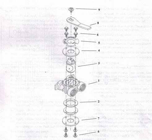
ProF1oSE Downflow water softener (5000SE)
By-Pass Valve Assembly, Brass parts list
Item No. Quantity Part No Description
I ………………………..I ………….17290 ………………By-Pass Valve Body, 3/4″
…………………………..1 ………….17290NP…………….By-Pass Valve Body, 3/4″, Nickel Plate
……………………………. 1 ………….13399 ………………By-Pass Valve Body, 1″ …………………………….I………….13399NP…………….By-Pass Valve Body, 1″, Nickel Plate
2 ………………………..1…………..11726 ………………Seal, By-Pass
3 …………………………..I ………….11972 ………………Plug, By-Pass
4 ……………………………..I ………….11978 ………………Side Cover
5 ……………………………. 1 …………. 13604-01 ……………. Label
6 …………………………….8………….15727 ………………Screw
7 …………………………….1 ………….11986 ………………Side Cover
8 …………………………….1 ………….11979 ………………Lever, By-Pass
9 ……………………………I ………….11989 ………………Screw, Hex Head, 1/4-14
ProFLoSE (5000SE FLECK) WATER SOFTENER
Parts list for ¾” turbine meter assembly
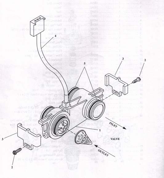
ProFLoSE (5000SE FLECK) WATER SOFTENER
Parts list for ¾” turbine meter assembly
ASSY NO. 60626-01
Item No. Quantity Part No Description
I ……………………………I 19797 ……………..Meter Assembly, Turbine
2………………………….2 ………….13314……………..Screw,HexWasher,8-18×5/8ó
3………………………….2 ………….19569………………Clip, Flow Meter
4…………………………..1 .19791-01 …………… Meter Cable Assembly, Turbine
5…………………………..4 13305……………… O-Ring,-119
6 …………………………..1 ..14613……………… Flow Straightener
U.S.A
ProF1oSE Downflow water softener (5000SE)
Service Instructions
- TO REPLACE BRINE VALVE, INJECTORS,AND SCREEN
- Turn off water supply to conditioner:
- If the conditioner installation has a “three valve” by-pass system, first open the valve in the by-pass line, then close the valves at the conditioner inlet and outlet.
- If the conditioner has an integral by-pass valve, put it in the by-pass position.
- If there is only a shut-off valve near the conditioner inlet, close it.
- Relieve water pressure in the conditioner by stepping the control into the backwash position momentarily. Return the control to the service position.
- Unplug electrical cord from outlet.
- Disconnect brine tube and drain line connections at the injector body.
- Remove the two injector body mounting screws. The injector and brine module can now be removed from the control valve. Remove and discard brine body 0-rings.
6A. To replace brine valve.
- Pull brine valve from injector body, also remove and discard 0-ring at bottom of brine valve hole.
- Apply silicone lubricant to new 0-ring and reinstall at bottom of brine valve hole.
- Apply silicone lubricant to 0-ring on new valve assembly and press into brine valve hole, shoulder on bushing should be flush with injector body.
6B. To replace injectors and screen.
- Remove injector cap and screen, discard 0-ring. Unscrew injector nozzle and throat from injector body.
- Screw in new injector throat and nozzle, be sure they are sealed tightly. Install a new screen.
- Apply silicone lubricant to new 0-ring and install around oval extension on injector cap.
- Apply silicone lubricant to three new 0-rings and install over three bosses on injector body.
- Insert screws thru injector cap and injector. Place this assembly thru hole in timer housing and into mating holes in the valve body. Tighten screws.
- Reconnect brine tube and drain line.
- Return by-pass or inlet valving to normal service position. Water pressure should now be applied to the conditioner, and any by-pass line shut off.
- Check for leaks at all seal areas. Check drain seal with the control in the backwash position.
- Plug electrical cord into outlet.
- Set time of day and cycle the control valve manually to assure proper function. Make sure control valve is returned to the service position.
- Make sure there is enough salt in the brine tank.
- Start regeneration cycle manually if water is hard.
TO REPLACE TIMER
- Follow Steps A.1 through A.3.
- Remove the control valve back cover. Remove the control valve front cover. Disconnect the meter dome signal wire from the front cover and feed it back through the control.
- Remove screw and washer at drive yoke. Remove timer mounting screws. The entire timer assembly will now lift off easily.
- Put new timer on top of valve. Be sure drive pin on main gear engages slot in drive yoke.
- Replace timer mounting screws. Replace screw and washer at drive yoke. Replace meter signal wire.
- Return by-pass or inlet valving to normal service position. Water pressure should now be applied to the conditioner, and any by-pass line shut off.
- Replace the control valve back cover.
- Follow Steps A.12 through A.15.
- TO REPLACE PISTON ASSEMBLY
- Follow Steps A.1 through A.3.
- Remove the control valve back cover. Remove the control valve front cover. Disconnect the meter dome signal wire from the front cover and feed it back through the control.
- Remove screw and washer at drive yoke. Remove timer mounting screws. The entire timer assembly will now lift off easily. Remove end plug retainer plate.
- Pull upward on end of piston yoke until assembly is out of valve.
U.S.A.
ProF1oSE Downflow water softener (5000SE)
Service Instructions (Contd.)
TO REPLACE PISTON ASSEMBLY (Cont’d.)
- Inspect the inside of the valve to make sure that all spacers and seals are in place, and that there is no foreign matter that would interfere with the valve operation.
- Take new piston assembly as furnished and push piston into valve by means of the end plug. Twist yoke carefully in a clockwise direction to properly align it with drive gear. Replace end plug retainer plate.
- Place timer on top of valve. Be sure drive pin on main gear engages slot in drive yoke.
- Replace timer mounting screws. Replace screw and washer at drive yoke.
- Return by-pass or inlet valving to normal service position. Water pressure should now be applied to the conditioner, and any by-pass ‘line shut off.
- Replace the control valve back cover.
- Follow Steps A.12 through A.15.
- TO REPLACE SEALS AND SPACERS
- Follow Steps A.1 through A.3.
- Remove the control valve back cover. Remove the control valve front cover. Disconnect the meter dome signal wire from the front cover and feed it back through the control.
- Remove screw and washer at drive yoke. Remove timer mounting screws. The entire timer assembly will now lift off easily. Remove end plug retainer plate.
- Pull upward on end of piston rod yoke until assembly is out of valve. Remove and replace seals and spacers.
- Take piston assembly and pish piston into valve by means of the end plug. Twist yoke carefully in a clockwise direction to properly align it with drive gear. Replace end plug retainer plate.
- Place timer on top of valve. Be sure drive pin on main gear engages slot in drive yoke.
- Replace timer mounting screws. Replace screw and washer at drive yoke.
- Return by-pass or inlet valving to normal service position. Water pressure should now be applied to the conditioner, and any by-pass line shut off.
- Replace the control valve back cover.
- Follow Steps A.12 through A.15.
- TO REPLACE METER
- Follow Steps A.1 through A.3.
- Remove two screws and clips at by-pass valve or yoke. Pull resin tank away from plumbing connections.
- Pull meter module out of control valve.
- Remove signal wire from meter module, (snap tab on end opposite wire cable).
- Apply silicone lubricant to four new 0-rings and assemble to four ports on new meter module.
- Install signal wire into new meter module.
- Assemble meter to control valve. Note, meter portion of module must be assembled at valve outlet.
- Push resin tank back to the plumbing connections and engage meter ports with by-pass valve or yoke.
- Attach two clips and screws at by-pass valve or yoke. Be sure clip legs are firmly engaged with lugs.
- Return by-pass or inlet valving to normal service position. Water pressure should now be applied to the conditioner, and any by-pass line shut off.
- Check for leaks at all seal areas.
- Follow Steps A.12 through A.15.
U.S.A.
ProF1oSE Downflow water softener (5000SE)
Troubleshooting Guide
SYMPTONS PROBABLE CAUSE CORRECTION
1Softener fails to regenerate A. Cord plugged into intermittent A. Connect to constant power
automatically. or dead power source. source.
- Disconnected meter cable. B. Reconnect cable.
- Defective power cord. C. Replace cord.
- Defective timer, meter or sensor. D. Replace or repair
- Regeneration at wrong time. A. Timer improperly set, due to Power failure. A. Reset timer.
- Loss of capacity. A. Increased raw water hardness. A. Reset unit to the new capacity.
- Brine concentration and/or quantity. B. Keep brine tank full of salt at all times. Clean it
yearly. Salt may be bridged. If using a salt grid plate
ensure refill water is over it.
- Resin fouling. C. Call dealer, find out how to confirm it, clean the resin and prevent future fouling.
- Poor distribution, Channeling (uneven bed surface). D. Call dealer. Check distributors and
backwash flow.
- Internal valve leak. E. Call dealer. Replace spacers, seals and/or piston.
- Resin age. F. Call dealer. Check for resin oxidation caused by Chlorine. Mushy resin.
- Resin Loss. G Call dealer. Check for correct bed depth. Broken distributors. Air or gas in bed:
Well gas eliminator Loose brine line.
- Poor water quality A. Check items listed in #3.
- Bypass valve open. H. Close by-pass valve.
- Channeling. I. Check for too slow or high service flow.
Check for media fouling.
- High salt usage. A. High salt setting. A. Adjust salt setting.
- Excessive water in brine tank. CORRECTION B. See symptom No. 7.
Troubleshooting Guide (Cont’d.)
SYMPTONS PROBABLE CAUSE CORRECTION
- Loss of water pressure. A. Scaling/Fouling of inlet pipe.
- Fouled resin. E. Clean the resin. Pretreat to prevent.
- Improper backwash. F. Too many resin fines and/or sediment.
Call dealer, reset backwash flow rate,
and/or adjust time
- Excessive water in brine tank Plugged Drain Line. A. Check flow to drain. Clean flow
and/or salty water to service. control.
- Dirty or damaged brine valve. B. Clean or replace brine valve.
- Plugged injector. C. Clean injector and replace screen.
- Low inlet pressure. D. Increase pressure to allow injector to perform properly (20 psig
minimum.)
- Timer not cycling. E. Replace timer.
- Softener fails to use salt.
- Plugged/restricted drain line. A. Clean drain line and /
or flow control.
- Injector is plugged. B. Clean or replace injector and screen.
- No water in brine tank. C. Check for restriction in BLFC. Ensure safety float is not stuck.
- Water pressure is too low. D. Line pressure must be at least 20 psi.
- Brine line injects air during brine draw. E. Check brine line for air leaks.
- Internal control leak. F. Call dealer. Check piston, seals and spacers for scratches and dents.
- Control cycles continuously. A. Faulty timer. A. Replace timer.
- Continuous flow to drain. A. Foreign material in control. A. Call dealer. Clean valve, rebuild unit.
- Internal control leak. B. Same as above C. Valvejammed in brine or backwash position.
- Timer motor stopped or jammed. Clean or replace pipeline. Pretreat to prevent.
- Replace timer motor.
U.S.A.
ProF1oSE Downflow water softener (5000SE)
Service Assemblies
AIR CHECK SERVICE EQUIPMENT
60002 Residential Type, #500 12664 1/4″ Nut Driver
12736 Stuffer Tool (Seals & Spacers)
BRINE LINE FLOW CONTROLS (BLFC) 12874 Seal Hook
60022-12 Model 1600 with .125 GPM Flow Control 13061 Puller Tool (Seals & Spacers)
60022-25 Model 1600 with .25 GPM Flow Control 16908 Phillips Bit Large, 1/4″ Drive
60022-50 Model 1600 with .50 GPM Flow Control 16909 5/16″ Magnetic Socket, 1/4″ Drive
60022-00 Model 1600 with 1.00 GPM Flow Control 16174 Silicone Grease, 2 oz. Tube
16586-8 Silicone Grease, 8 lb. Pall
BRINE VALVE 40157 Wrench, Plastic By-Pass
60032 Brine Valve Assembly 60135-ProFIoSE Service Repair Kit
COLLECTORS, UPPER TIMER
18280 1″ Standard Slot (010 – .012 slot size) 60652-00 Timer, ProFloSE, Downflow
18280-01 1″ Wide Slot (.019 -.022 slot size)
18280-02 1″ Narrow Slot (.007 -.009 slot size) YOKES
13708 3/4″NPT
COVER 13708-10 314″ BSP
18260-00 Smoked Cover 13708NP 3/4″ NPT, Nickel Plated
13708-IONP 314″ BSP Nickel Plated
DISTRIBUTORS 13708-45 3/4″ Sweat
60795-00 1″ x 72″ Standard Slot 13708-45NP 3/4″ Sweat, Nickel Plated
(.010 -.012 slot size) 13708-40 1″ Sweat
60795-01 1″ x 72″ Wide Slot (.019 -.022 slot size) 13708-40NP 1″ Sweat, Nickel Plated
60795-02 1″ x 72″ Narrow Slot 13398 1″ NPT
(.007 – .009 slot size) 13398-10 1″ BSP
13398NP 1″ NPT, Nickel Plated
DRAIN LINE FLOW CONTROLS 13398-JONP 1″ BSP Nickel Plated
60705-XX Drain Line Flow Control 18706 1″ Plastic, MNPT
(From .6- 7.0 gpm) 18706-10 1″ Plastic, MBSP
60706-XX Drain Line Flow Control w/Quick 18706-02 3/4″ Plastic, MNPT
Connect (From 8 – 15 gpm) 18706-12 314″ Plastic, MBSP
60700-XX Drain Line Flow Control Only 19275 3/4″ 900 Angle, NPT
(8- 15 gpm) 19275-10 314″ 90° Angle, BSP
19275NP 3/4″ 90° Angle, NPT, Nickel Plated
FLOATS 192 75-I0NP 314″ 90° Angle, BSP Nickel Plated
60068 2310 Float 19275-45 3/4″ 90° Angle Sweat
19275-45NP 3/4″ 90° Angle Sweat, Nickel Plated
FLOW CONTROL WASHERS 19620-01 90° Adapter Coupling
Brine Line Flow Controls
17307 .125 GPM BYPASS
12094 .25 GPM 60040 3/4″ Bypass NP’!’
10759 .50 GPM 60040NP 3/4″ Bypass NP’!’, Nickel Plated
12097 1.00 GPM 60041 1″ Bypass NP’!’
6004 INP 1″ Bypass NFL Nickel Plated
60049 3/4″ Bypass, Plastic
Service Assemblies (Cont’d.)
DRAIN LINE FLOW CONTROLS METER MODULE
19153 .06 GPM
19152 .08 GPM
19151 1.0 GPM
12085 1.2 GPM
19150 1.3 GPM
12086 1.5 GPM
19149 1.7 GPM
12087 2.0 GPM
12088 2.4 GPM
12089 3.0 GPM
12090 3.5 GPM
12091 4.0 GPM
19147 4.5 GPM
12092 5.0 GPM
17814 6.0 GPM
12408 7.0 GPM
17943 8.0 GPM
17944 9.0 GPM
16529 10 GPM
16735 12 GPM
16736 15 GPM
18272-000 #000 Brown Injector
18272-00 #00 Violet Injector
18272-0 #0 Red Injector
18272-1 41 White Injector
18272-2 #2 Blue Injector
60626 3/4″ Turbine Meter
PISTON
60115-00 Piston Assembly
POWER HEAD
60201-001 Powerhead
SAFETY BRINE VALVE 60014 2310 Plastic
SALES & SERVICE AIDS
40276 Spec Sheet
40272 Service Manual
16700 Product Line Brochure
SEALS & SPACERS
60120 Seal and Spacer Kit
#6
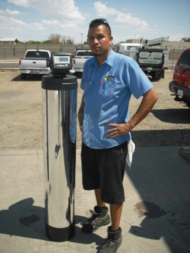
08.08.15 GE Autotrol (Aqua Pure)
This unit is also known as:
Logix 268/760 Meter Water Softener – 64,000 Grain Capacity
Logix 268/760 Meter Water Softener – 48,000 Grain Capacity
Logix 268/760 Meter Water Softener – 40,000 Grain Capacity
Logix 268/760 Meter Water Softener – 32,000 Grain Capacity
Most common problems:
If this valve has the collar (no threads holding the valve to the tank):
The bypass valve crachs.
Under high water pressure; the collar will separate from the tank and cause a major flood.
We have many of the recycled parts to fix this unit.
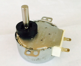
AUTOTROL (LOGICS) DRIVE MOTOR 268/760 PART # 1235361 $40.00 PLUS TAX (post date 04.21.15 8:36 AM)
07.15.15 8:59 AM
Series 1265 Bypass Valve
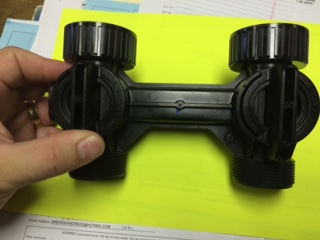
Price $45.00 plus tax; new and in stock now. It is always a great idea to call us (480) 969-7251 and confirm your availability to this part. Restocking takes two days.
This bypass valve has been famous with our customers. Many water softeners installed in Arizona (water treatment dealer in Phoenix, AZ; Buckeye AZ; San Tan Valley, AZ) have this style bypass valve.
These are other descriptions of this valve:
1265 Bypass Valve Pentair residential water filtration, Performa 1040930, Autotrol 1265 Bypass Valve Assembly, Noryl Plastic 1040930 263/268 (This bypass valve assembly is compatible with all Autotrol 263, 268, 269, 273, and 278 series), Technetics 1100, part # 1040930. 1040930 – US Water Systems. bypass for GE & Pentair.
Installation and Operation Instructions
Note: When installing, be certain to leave slack in the vertical inlet and outlet lines connected to the bypass valve. The softener must not be supported by the plumbing lines.
Installation
Step 1:
Verify that there is a gasket secured inside of the inlet and outlet union nuts of the bypass. Then, thread the bypass to the valve control body, hand-tightening both union nuts simultaneously. It is not necessary to lubricate or use sealant on the rubber gaskets or union nuts.
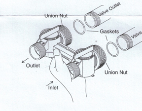
Step 2:
Insert tailpieces through union nuts. Attach tailpieces into inlet and outlet piping. Place the rubber gasket into the union nut and thread to bypass valve body. It is not necessary to lubricate or use sealant on rubber gasket or union nuts.
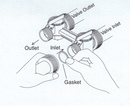
Step 3:
After all plumbing connections have been made, follow the start-up procedure in the owner’s manual for initial set-up.
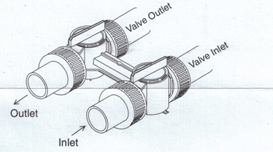
Operation
To bypass the conditioner with the 1265 bypass valve, rotates the handles clockwise so they are both perpendicular to the flow path of the inlet and outlet water stream, as shown below.
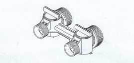
Source:
2009 Pentair Residential Filtration, LLC P/N 1223024 Rev. D JA09. My family sells many Pentair parts and equipment. I am humbly requesting that Pentair allows us to copy and share this information with potential Pentair clients. The information above represents this effort: to sell more of their parts and products.
112515 10:24 AM
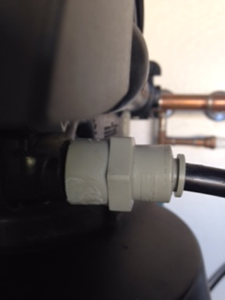
This is an image of a 3/8″ FTP x 3/8″ John Guess fitting (on an Aqua Pure CWS200ME CWS Series 13.5 GPM Water Softener System With Bypass Valve, AWS300M Cuno ‘a 3M company’, NWS Series Residential Softeners / 3M Cuno Aqua-Pure # NWS100 / NWS150 / NWS200 / NWS100M / NWS150M / NWS200M).
. A man called yesterday because his was leaking. We changed the O-rings in our recycled part and will fix his unit.
#7
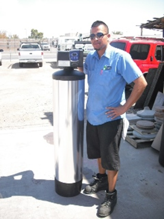
08.08.15 Fleck 7000 Water Softener. We have all the parts necessary to service and repair this unit (including the cation resin).
09.02.14 A common problem we are finding on the Fleck 7000 , on this unit, is that it is not reading the gallons (the gallons do not count down). This can cause hard water. The solution; replace the turbine. These turbines are problematic and need to replaced often.
Another problem we are experiencing with this type unit is error codes. If you ever receive an error code on this unit please call us (480) 969-7251 or e mail me This email address is being protected from spambots. You need JavaScript enabled to view it.This email address is being protected from spambots. You need JavaScript enabled to view it.
#8
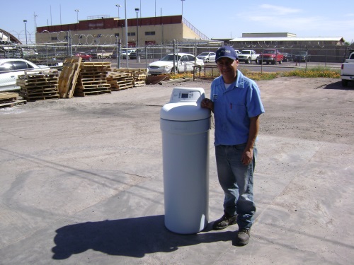
08.08.15 This is a GE Smart Water – water softener. Below is the valve diagram and several parts that we recycle. We will carry these parts (described below) and provide service on this unit.
Some of the parts we will carry new.
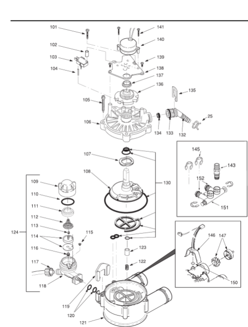
This is the valve diagram for the GE Smart Water – Water softener. Please expand this image and call us if you need parts or service on this unit. It is true these units are mostly too small for the hard Arizona water. However, our onus is to become experts on all the different types of water softeners that are being sold in the Phoenix Metro and surrounding areas so people can depend on us to take care of all your water treatment needs.
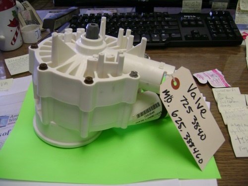
08.08.14 GE Smart Water Valve part #121 (model # 625 388460). We have 2 of these parts in stock and the price is $15.00 plus tax.
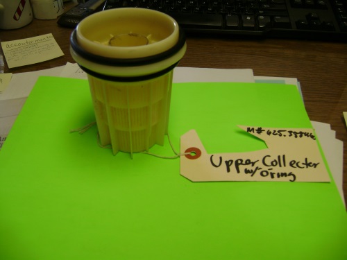
08.08.15 GE Smart Water Upper Collector with o- ring (model # 625 388460). We have 2 of these parts in stock and the price is $2.00 plus tax.

08.08.15 GE Smart Water 1″ Bypass adapter (model # 625 388460). We have 2 of these parts in stock and the price is $2.00 plus tax.
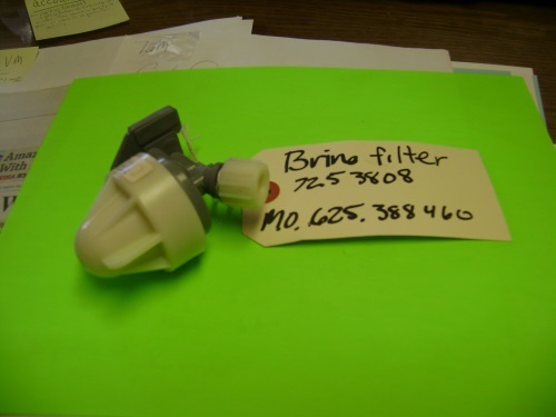
08.08.15 GE Smart Water Brine Filter part #124 (model # 625 388460). We have 2 of these parts in stock and the price is $2.00 plus tax.
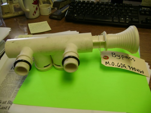
08.08.15 GE Smart Water By pass valve part #151 (model # 625 388460). We have 2 of these parts in stock and the price is $20.00 plus tax. This is the most popular part that we sell. They fail frequently.
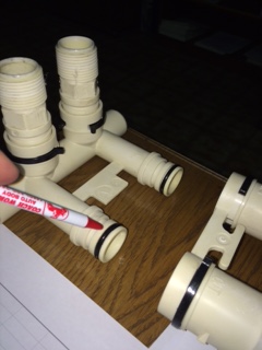
082615 4:40 PM
Large O ring for Bypass valve – GE (General Electric)/ Kenmore (Sears) water softener model number 625388460
Part number WS03X10011
Price $5.50 plus tax
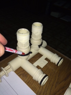
Small clip for Bypass valve – GE (General Electric)/ Kenmore (Sears) water softener model number 625388460
Part # WS60X10004
Price $9.00 plus tax
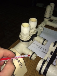
Small O ring for Bypass valve – GE (General Electric)/ Kenmore (Sears) water softener model number 625388460
Part number WS03X10025
$6.50 plus tax

Large clip for Bypass valve – GE (General Electric)/ Kenmore (Sears) water softener model number 625388460
Part # WS60X10008
Price $9.00 plus tax
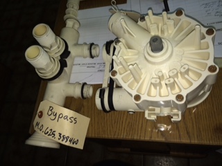
Bypass valve – GE (General Electric)/ Kenmore (Sears) water softener model number 625388460
Used $25.00 plus tax
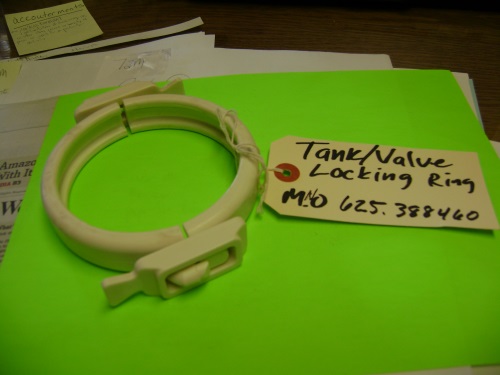
08.08.15 GE Smart Water – water softener Tank/ Valve Locking Ring (model # 625 388460). We have 2 of these parts in stock and the price is $3.00 plus tax. This part fails and can cause a flood to occure in a home.
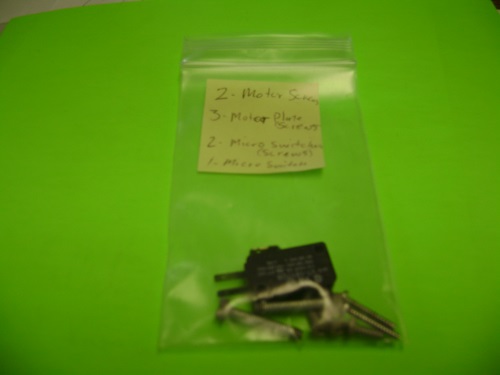
08.08.15 GE Smart Water – water softener 6 motor plate screws part #104, 4 micro switches (screws) part #101, 2 micro switches part #103 (model # 625 388460). We have 2 of these parts (all of these components) in stock and the price is $5.00 plus tax.
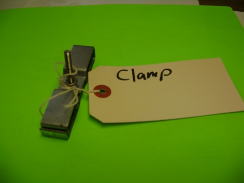
08.08.15 GE Smart Water – water softener electrical ‘grounding’ clamp (model # 625 388460). We have 2 of these parts in stock and the price is $0.50 plus tax.
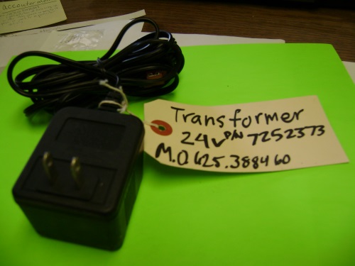
08.08.15 GE Smart Water – water softener transformer (part number 7252373) for the (model # 625 388460). We have 2 of these parts in stock and the price is $5.00 plus tax.
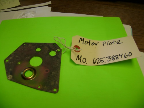
08.08.15 GE Smart Water – water softener motor plate part #138 (model # 625 388460). We have 2 of these parts in stock and the price is $0.50 plus tax.
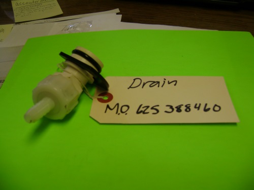
08.08.15 GE Smart Water – water softener drain for the (model # 625 388460). We have 2 of these parts in stock and the price is $3.50 plus tax.
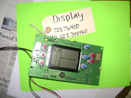
08.08.15 GE Smart Water – water softener digital display (model # 7257640D) for the (model # 625 388460). We have 2 of these parts in stock and the price is $15.00 plus tax.
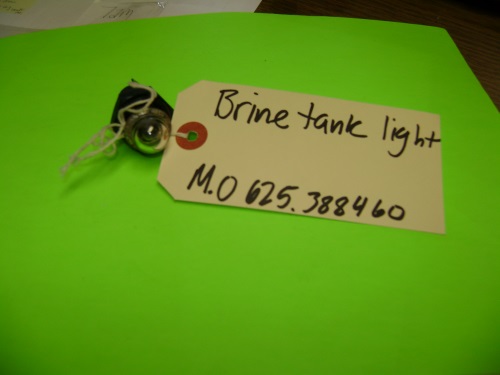
08.08.15 GE Smart Water – water softener brine tank light for the (model # 625 388460). We have 2 of these parts in stock and the price is $1.00 plus tax.
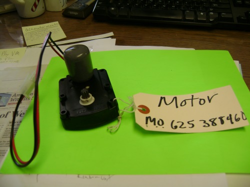
08.08.15 GE Smart Water – water softener motor part #140 (model # 625 388460). We have 2 of these parts in stock and the price is $10.00 plus tax.
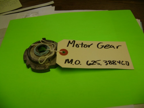
08.08.15 GE Smart Water – water softener motor gear part #136 (model # 625 388460). We have 2 of these parts in stock and the price is $10.00 plus tax.
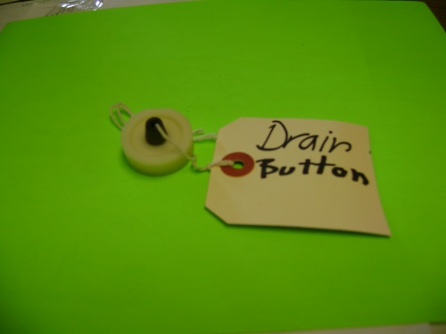
08.08.15 GE Smart Water – water softener drian button part #114 (model # 625 388460). We have 2 of these parts in stock and the price is $1.50 plus tax.
07.14.15
these are miscellaneous parts we carry for this unit:
Seal O-ring PS 8759074 for this GE Water Softener GXSF30 unit
#9
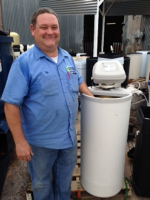
09.16.14 12:02 AM
GE Smart Water water softener
Model number: GXSS17Z01
#10
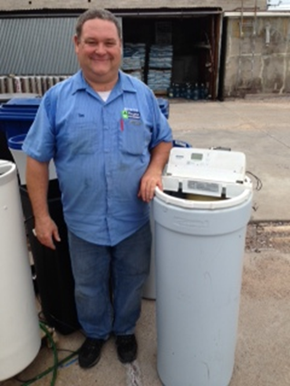
Kenmore Ultra Soft 180 water softener
Model number: 625.388180
#11
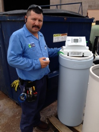
Kenmore Ultra Soft 400 water softener
Model number: 625.388450
this is the impeller part which measures the water flow
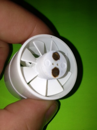
This impeller part (used) is $5.00 plus tax.
This is the inside area of this impeller. It is disintegrated because of the use and high chlorine content of our Phoenix metro water.
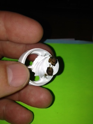
Because of the high chlorine content of our Phoenix metro water; we are finding that the tipping point on all residential water softener is 5 years. At this point many of the components are disintegrating and the cation resin material will cause low water pressure and plumbing problems because of cation resin oxidation. Therefore, many people are finding that our $30/mo plus tax (64,000 grain) rental soft water program is very popular and famous because it is affordable, efficient and dependable. There is more information about our rental soft water program discussed at this web page: http://www.azh2o.com/rent-a-water-softener-unit
09.22.14
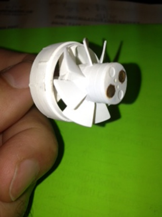
This is the same part in good condition (compare and contrast). The chlorine in the Phoenix Metro Arizona Water (including Buckey Arizona and Surprise Arizona) is ominous. Our company has developed convenient and affordable rental water treatment processes to remove this chlorine for you (for your home and business).
#12
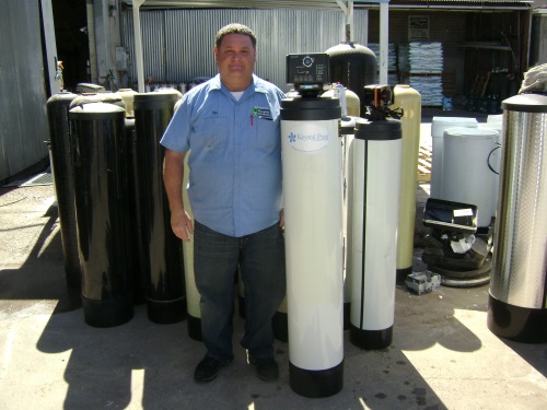
08.08.14 This is Tom (our most veteran technician of over 27 years); standing by a Krystal Pure Autotrol water softener. Many of these units are sold in the Lowe’s Hardware stores. We have all the parts required to fix these units. We are very qualified to service all Autotrol water softeners and all GE water softeners.
The main ingredient of the water softener is the cation resin material. We sell this by the cubic foot.
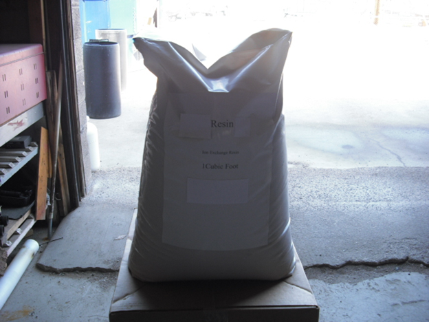
1 cubic feet of cation resin material
$125.00 plus tax
The quality and discription of this material is described on this web page:http://www.azh2o.com/index.php?option=com_content&view=article&id=100
Because of all the chlorine in our Phoenix metro water; we are finding the tipping point on this cation resin material is 5 years. We have used scientific method to determine that cation resin material is removing 50% of all chlorine in the Phoenix metro water. We see this as a great advantage to cation resin. This fact (cation resin removes 50% of all chlorine ‘the resin manufactures say “it dissipates the chlorine” ‘) gives this cation resin material higher value in Gilbert, Mesa, Phoenix, Buckeye, Apache Junction (and all surrounding cities in Phoenix Metro Arizona). Many people are finding our $30/mo plus tax residential rental water softener program to be of great efficacy and financial benefit. This process and program is described on this web page: http://www.azh2o.com/rent-a-water-softener-unit
This cation resin material is so popular that we purchase this material by the pallet. We utilize our Bobcat to unload this material and place this in our factory.
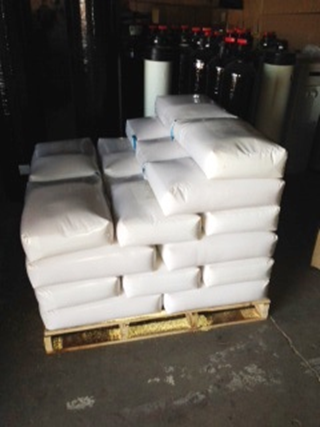
Will we purchase higher quantities of this cation resin material as time passes (right now we purchase one pallet each month)? Indubitably. As we experience the Phoenix metro area of Arizona grow to 7 million people (right now there is 4.33 million people; they say 7 million people will be here within 15 years) we expect this cation resin material to stay famous in our ranks. We continue to purchase better resin as the chlorine content of our Phoenix metro water increases (this is called crosslinking – discussed on this web page:http://www.azh2o.com/index.php?option=com_content&view=article&id=100).
#13 H2O Concepts Water Treatment/ Whole House No Salt Device
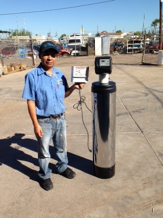
H2O Concept water treatment equipment with H2o Concepts Technology – AMP Force ™
slightly used (used for only two months) $200.00 plus tax ‘complete unit’
H2O CONCEPT
We removed this H2O Concepts unit (only 2 months old) from a house. The people whom gave us this unit were not happy with the water treatment performance. They said that this unit does not provide soft water. Therefore, this H2O Concepts water treatment unit does not give you the same benefits that soft water provides. The only way to have soft water is to have a water softener unit that utilizes cation resin as the water cleaning media. The customer chose for us to install a portable exchange water softener. They are very happy with with the results of our portable exchange water softener service. The people who bought this H2O Concepts could not get their money returned (after 2 months). They informed me that they invested more than $4,000.00 in this product. By the way, Boyett’s Family return policy is: if you are not completely satisfied with our rental water treatment program – I will return your installation fee and 3 months of the rental fees. Indubitably.
We decided to explicate this H2O Concepts water treatment unit. We decided to analyze this unit in great detail and study each individual component.
Our onus is to sell these used H2O Concepts components. When we accumulate enough parts we will rent these units for $30/month plus tax. We will change these units out every 5 years. The material that is filled in the media tank is called KDF. This material has a tipping point (a point of saturation). We feel this tipping point is 5 years.
Here is an image of the media that we extracted from this H2O Concepts unit.
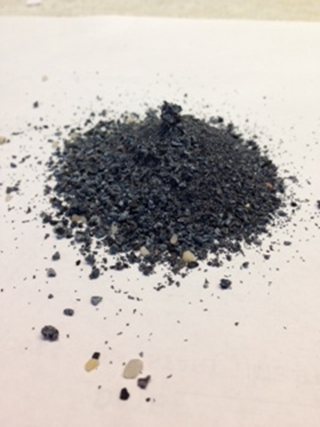
The main point of this story is this: this material must be changed periodically. How often will this media need to be changed? We will soon provide you a mathematical calculation to determine the number of gallons that can be cleaned by this material and the approximate time period this material will last. I can tell you this – this media will in no way last 10 years. As I understand; the customers who have been sold this product say they have been told 10 years to change this media. NO WAY. This information is apocryphal. As a rule of thumb – 1 cubic foot of carbon will dechlorinate about 1,000,000 gallons of water. Figure one person utilizes 70 gallons of water per day (based upon the standard of our water treatment industry). The H2O Concepts water treatment unit contains about 1 cubic foot of carbon.
posted 10.10.14 5:34 PM
We spoke with a person who is very familiar with the manufacturing of the H2O Concepts unit. They said that only 2-3 pounds of this material is included in this unit.
According to this water treatment expert; this amount of quantity (2-3 pounds of KDF) does not perform an effective water treatment function.
If KDF material is to be used effectively – a separate tank of KDF media would be filled with1/3 of a cubic foot ( this equals 57 pounds). In its own vessel (PUT IN to a 8” to 9” tank) the KDF will be proper back washed.
Why does this company even bother placing 2-3 pounds of KDF in the tank? Good question. The word hyperbole comes to my mind.
When we removed the KDF material from the H2O Concepts unit; it was in the configurations of clumps. Clumps of KDF will serve no purpose. The reason that the KDF (that we removed) clumped up – it needs to be placed in a separate vessel and back washed separately. This material has to be back washed at such a high rate that the noise makes this process non feasible (because of the noise created when the material is back-washing).
The purpose of KDF is:
Removal of heavy metals and removal of chlorine.
However, if there is not enough material to begin – this process becomes apocryphal.
When we removed this material from the H2O Concepts it was in clumps and likely completely ineffective.
Based upon technical information I read on the web page of H2O Concepts they indicated that their electrical technology changes the calcium bi carbonate to carbonate. As I understand from other water treatment professionals – this is the antithesis of the desired result. Good water treatment process will change calcium carbonate to bicarbonate. Calcium bicarbonate is less likely to adhere to the fixtures.
As an alternative to this H2O Concept; we feel that we have a more effective green water treatment approach with our Filtersorb SP3. This is a non-salt unit; it does not utilize any electricity.
Here is a link on our Filtersorb water treatment technology: http://azh2o.com/filtersorbsp3
04.13.15 11:14 AM
If you own H2O Concept water treatment equipment we can help you maintain this unit. The carbon media (included in the tall cylindrical tank) should be changed every five years and the valve rebuilt. In the future we will add the prices for these parts and service here. The valve that H2O Concept utilizes is a Fleck 5600 water softener valve. This is a very ordinary valve and we carry all the parts and can provide the service to these H2O Concept water treatment units. All the components on these units are familiar to us. H2O Concepts is said to utilize an AMP Force™ to facilitate a portion of the water treatment process. We plan to collect the (used/recycled) electronic components and stock these for your convenience.
In the H2O Concepts Technology description they refer to: “H2o Concepts whole house water filtration systems plus AMP Force™ uses proven media filtration with energy to address your hard water problem(s).”
The media they utilize
KDF
Carbon
Coconut Shell GAC (Granular Activated Carbon)
Quartz
None of these media (which are added to the H2o Concepts whole house water filtration systems (and comprise the H2o Concepts Technology) will remove hardness (calcium and magnesium ions)).
The other part of their H2o Concepts Technology is an energy technology in which they refer to as this: AMP Force™.
Here is a comment about this AMP Force ™ by a respected water treatment expert in Arizona:
Scaling in water is a natural reaction between calcium or magnesium and sulfates or carbonates in the water. The reaction is driven by the chemistry of molecules combining to form a lower energy state substance. This is a natural process of nature in which substances combine to go to a lower energy state. An example would be calcium (CA+2) + sulfate (SO4 -2) = CaSO4, Calcium Sulfate. Calcium Sulfate is a major component of water scaling. It is insoluble in water and will leave an undesirable residue in the piping that will eventually weaken its structure. I am not aware of any energy or force capable of reversing this process with the exception of an extremely high energy electrical current that would be very dangerous. In my 30 years of experience in the water purification industry, I have never observed a process that would economically reverse this natural process.
On the other hand, conventional water softening, which is 100 years old, accomplishes water scale reduction by exchanging the calcium and magnesium for sodium (NA+1) by means of a charged resin bead. The resulting substance, NaSO4, is very soluble in water and will leave a very small amount of residue in the piping. I believe, after 30 years in the business, that conventional water softening is still the only viable process to reduce water scaling.
A paraphrase ‘if I may be so bold’: he is saying there is no way that AMP Force ™ can accomplish what H2o Concepts Technology is promising. H2o Concepts Technology is not scientifically accurate. This is the end of my paraphrase.
042315 12:20 PM
I just learned from one of our customers (#192021) that H2O Concept water treatment equipment with H2o Concepts Technology – AMP Force ™; one of their salesmen is disseminating false information regarding salt. This H2O Concept water treatment equipment with H2o Concepts Technology – AMP Force ™ salesman told our customer that salt is bad for her skin.
Here is some information that dispels that notion.
In a book
Called Solve it with salt ; I found some interesting facts about salt and skin.
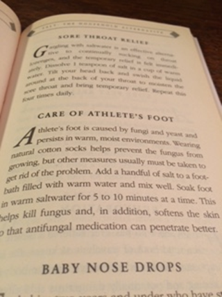
According to this book; salt does a fine job caring for athlete’s foot. It says:
Athlete’s foot is caused by fungi and yeast and persists in warm, moist environments. Wearing natural cotton socks helps prevent the fungus from growing, but other measures usually must be taken to get rid of the problem. Add a handful of salt to a footbath filled with warm water and mix well. This helps kill fungus and, in addition, softens the skin so that antifungal medication can penetrate better.
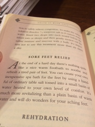
According to this book; salt does a fine job providing sore feet relief. It says:
At the end of a hard day there’s nothing quite like a nice warm footbath to soothe and refresh a tired pair of feet. You can create your own inexpensive spa bath for the feet by using a handful of ordinary table salt tossed into a small basin of water heated to your own level of comfort. It’s much more revitalizing than a plain basin of warm water and will do wonders for your aching feet.

According to this book; salt does a fine job providing relief for rough and chapped skin. It says:
Ordinary table salt can be used to create your own customized skin relief cream. To soften rough skin in such problem spots as feet, knees, and … (continued at the top of the page below) Elbows, combine ¼ cup salt, ¼ cup Epson salts, and ¼ cup vegetable oil, and massage the resulting paste into the dry skin for several minutes. After the cream has refreshed your skin it can be removed by bathing or showering.
According to this book; salt does a fine job removing dry skin. It says:
Salt can act as an abrasive to help remove dry and flaky skin. After bathing and while still wet, give yourself a massage with dry salt on a sponge, washcloth, or pumice stone. It removes dead skin particles, exposing the more radiant skin underneath, and it also aids the circulation.

According to this book; salt can be beneficial when applying a facial. It says:
Salt can be used to create an excellent revitalizing mixture to give yourself a home facial. First wash your face and apply warm, wet towels to the skin. Then apply a mixed solution of equal parts salt and olive oil, and gently massage the face and throat with long upward and inward strokes. Remove the mixture after 5 minutes and then rinse the face and apply your favorite face lotion.

The above image describes the importance and relevance salt has played in the development of our civilization. The first paragraph says “wars were fought over salt, and huge taxes were also levied on it. In some places, salt was in such high demand that it was minted into coins that were as valuable as gold and functioned as the basic currency for ancient civilizations.”
I humbly present to you that the owners and managers and sales people and the sales trainers (of H2O Concept water treatment equipment with H2o Concepts Technology – AMP Force ™) are not privileged to have access to this information. I can only wish that these people are not myopic and insular in their thinking. I hope these people appreciate the importance salt has played in the development of our great civilization and continue to appreciate salt for our health, happiness and wellness. However, I fear that the people of H2O Concept water treatment equipment with H2o Concepts Technology – AMP Force ™ are misleading many people in Arizona. We have had many indications that the people of H2O Concept water treatment equipment with H2o Concepts Technology – AMP Force ™; their intentions are not pure. They seem to misrepresent the soft water business; and our use of salt. The people of H2O Concept water treatment equipment with H2o Concepts Technology – AMP Force ™ call salt harmful and bad. However, salt is still of great value for health and preservation. We wish to reach out to these people and help them correct their course. There may still be time; we keep hoping.

110 surprising and ingenious household uses for salt by Patty Moosbrugger Three Rivers Press
- Solve it with salt 110 surprising and ingenious household uses for salt by Patty Moosbrugger Three Rivers Press
01.22.15 3:08 PM
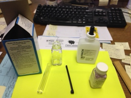
This is a Hach 5B soft water testing kit. Price $45.00 plus tax. We have three of these in stock (our office is located at 38 East 5th Avenue, Mesa AZ 85210).
If the water treatment equipment you have does not test soft – you don’t have soft water.
If the water softener you have does not test soft – we can help. We are happy to test your water at our factory for free. We are happy to inspect your water equipment. Our service fee is $85.00.
As the owner of this company I perform cation resin inspections in the evening (after 5:30 PM or on Saturdays) at no charge. We have made ‘testing and monitoring cation resin’ a company scientific experiment.
Our company intends to be harbingers; developing methods to keep your resin in pristine condition – affordably.
#14 04.13.15 10:42 AM
This is a by pass stem for a Culligan bypass valve. Most Culligan water softeners include a bypass valve. However, I responded to an emergency Culligan water softener leak last night (the water was running to the drain) and there was no bypass valve. The customer had to turn the water off to their house. This customer decided to rent a water softener from our company ($75 one time connection fee and $30/mo plus tax). We will indubitably include a bypass valve. We will also include our Boyett’s Family resin screen.
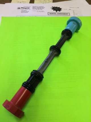
$10.00 plus tax – for used (recycled) Culligan water softener bypass stem. These are also used on Culligan rental water softeners.
In the future we plan to add used Culligan parts to our water softener parts inventory in hopes we can adopt orphans who need our Culligan water softener service and parts. We are always happy to answer any questions you have over the phone about all Culligan water softeners and Culligan reverse osmosis units.
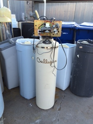
Culligan Aqua-sensor. Used unit for parts $10.00 plus tax
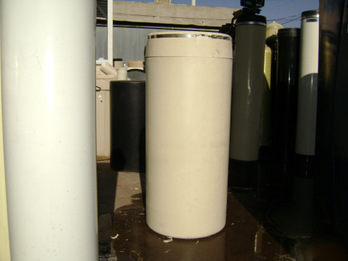
04.22.15 9:36 AM
This is a Culligan brine tank. A customer in Gilbert (Culligan Water Softener) called because their Culligan brine tank (Gilbert, Arizona 85295) was leaking. I stopped by her house very early this morning. Our customer was nice enough to call us because she currently rents their reverse osmosis from my family. She will now rent a water softener from my family. To learn more about our rental soft water program http://azh2o.com/rent-a-water-softener-unit ($75.00 one time connection fee; $30.00/month plus tax ‘we change the entire unit every 5 years).
#14.10
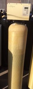
Culligan Medallist Plus Series 30, 45 and 60
Culligan Medallist Plus Series 30, 45 and 60
Valve part number 01016328
Price of valve $20.00 plus tax; this is a used part.

$10.00 plus tax. This is a used part.
Cul-Flo-Valv Bypass Culligan Medallist Plus Series 30, 45 and 60
When & How to Bypass
Your Water Culligan Medallist Plus Series 30, 45 and 60 Filter (Phoenix, AZ; Buckeye AZ; San Tan Valley, AZ; Scottsdale, AZ; Cave Creek, AZ)
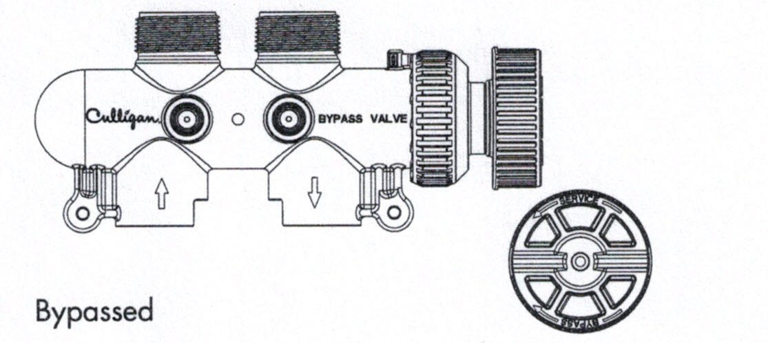
Medallist Series Bypass Valve
Culligan Bypass Valve
In the back of Culligan water filters is a Cul-Flo-VaIv® Bypass. To bypass unit, simply turn the blue knob clockwise. To return to soft water service, reverse the procedure – turn the blue knob counterclockwise.
To BYPASS, turn the blue knob clockwise (see directional arrow on end of knob) until the knob stops as shown.
DO NOT OVERTIGHTEN
To return to SERVICE, turn the blue knob counter-clockwise (see directional arrow on end of knob) until the knob stops as shown.
DO NOT OVERTIGHTEN
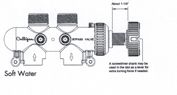
#14.15
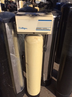
CULLIGAN ESTATE 2/2M WATER CONDITIONER
Estate 2 and 2M (8-96); CULLIGAN ESTATE 2/2M WATER CONDITIONER/ filter
Valve model number 01010091
Price of valve $20.00 plus tax; this is a used part.
Other descriptions for this water softener:
Estate 2 and 2M (8-96); CULLIGAN ESTATE 2/2M WATER CONDITIONER/ filter
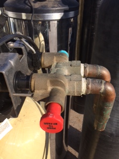
$10.00 plus tax; this is a used part.
CULLIGAN ESTATE 2/2M WATER CONDITIONER Bypass valve
When and how to bypass your Culligan
water conditioner. .
PUSH-BUTTON BY-PASS
To by-pass unit, simply push the Red knob (marked “Push to By-Pass”) all the way to your left. To return to soft water service, reverse the procedure – push the Blue knob (marked “Soft Water”) all the way to your right.
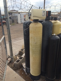
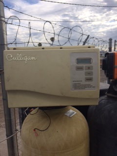
082615 5 PM
We have used parts for a
Culligan Medallist Plus Series® 30, 45 and 60 Water Softeners part number 01016390
Please call for prices and availability of parts (480) 969-7251. This is a water treatment system for San Tan Valley, AZ and Cave Creek, AZ.
#15
04.17.15 2:16 PM
We carry parts and provide service on the Water Boss Water Softener
Below is information about this Water Boss Water Softener unit and the used parts we have available. We have included the prices of these used parts (while supplies last).
Model 950
For City Water
22,000 Grain Capacity
This unit is sold at these stores:

![]()
Drive End Cap Assembly
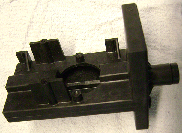
Drive Cap Assembly body $3.00 plus tax
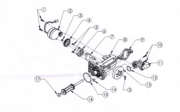
ITEM QTY PART NO. DESCRIPTION
1 2 90802 Screw
2 1 90217 Drive motor
3 2 9389 1/4 Hex Nut
4 1 93238 Drive Gear
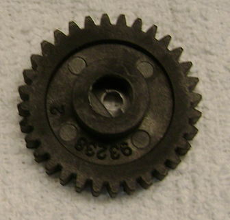
Drive gear Price $1.00 plus tax
5 2 90809 Screw
6 1 93219 Piston Slide Cam Cover
7 1 93217 Piston Slide Cam
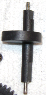
Piston Slide Cam Price $2.50 plus tax
8 1 93583 Drive End Cap
9 1 93216 Piston Slide
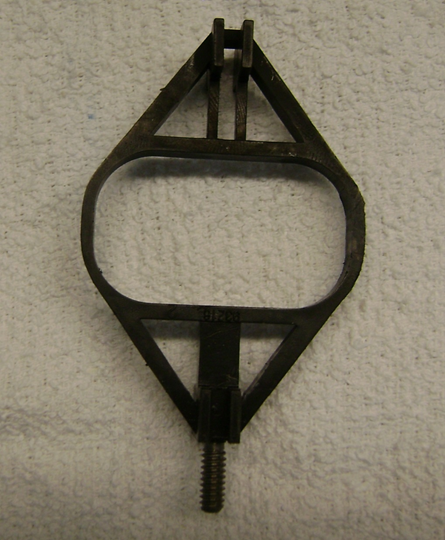
Piston Slide Price $1.50 plus tax
10 2 90818 Screw
11 1 93601-JG Brine Valve Housing Assembly
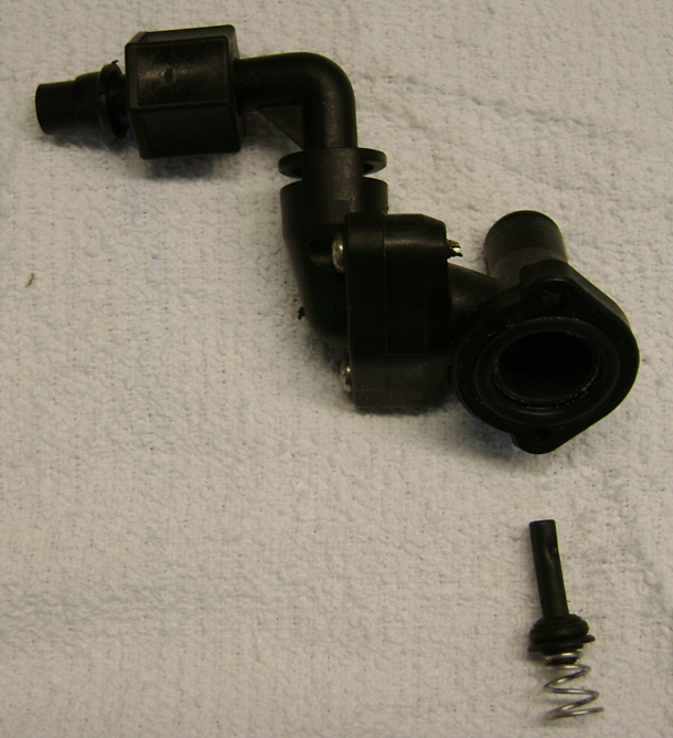
Brine Valve Housing Assembly Price $3.00 plus tax
12 1 93803 0- Ring
13 1 54502 Magnet Disk Assembly
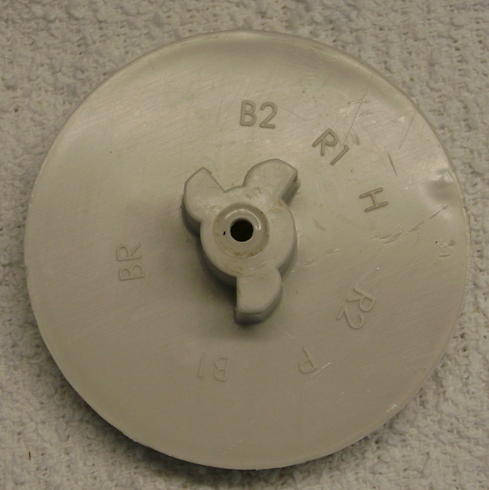
Magnet Disk Assembly Price $2.00
14 1 90828 0-Ring
15 1 93808 0-Ring
16 1 93522-A Drive Piston Assembly
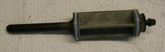
Drive Piston Assembly Price $1.50 plus tax
17 1 93839 Drain Gasket
Injector Assembly
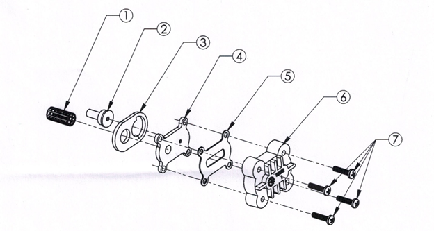
ITEM NO. QTY. PART NO. DESCRIPTION
1 1 93810 Injector Screen
2 1 93223 Injector Throat
3 1 93220 Injector Seal (Thick)
4 1 93221 Injector Nozzle
5 1 93232 Top Injector Seal (Thin)
6 1 93222 Injector Cap
7 4 90807 Screw
In and Out Adapter Assembly
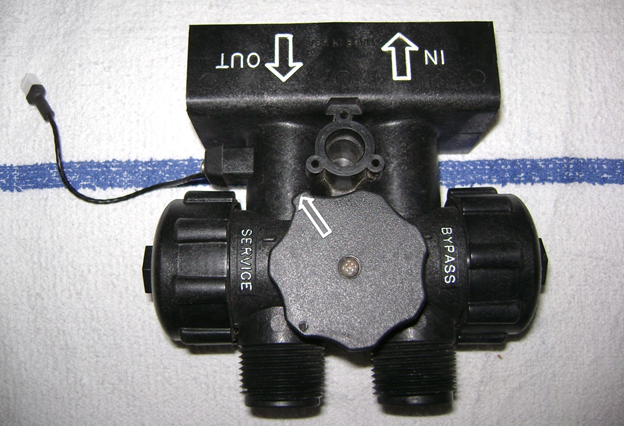
In and Out Adapter Assembly Price $10.00 plus tax
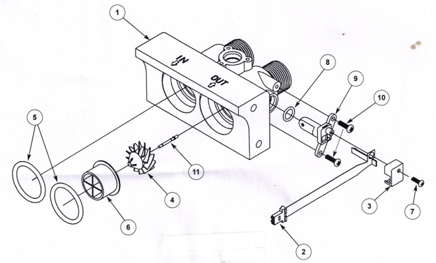
PART# DESCRIPTION QUANTITY
154131 3/4″ IO Adapter I
293858 Turbine Sensor Assembly I
390232 Turbine Sensor Cap I
490522 Turbine Assembly I
593838 “0” Ring 2
693229 Flow Director I
790809 Sensor Cap Screw I
890828 Test Port I Sensor Housing 0-ring I
993271 Turbine Sensor Housing I
1090802 Turbine Sensor Housing Screw 2
1190245 Turbine Axle 1
Drain End Cap Assembly
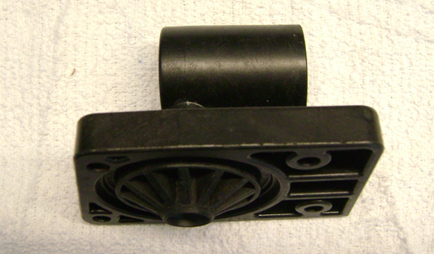
Drain End Cap Assembly Price $5.00 plus tax
FIGURE # PART# DESCRIPTION QUANTITY
1 90268 Drain End Cap (Threaded) I
2 H2086-5.0 Drain Line Flow Control Button I
H2086-3.0 Drain Line Flow Control Button I
3 90267 Retainer I
4 93808 “0” Ring 1
90614 Drain End Cap Assembly (1-4) 1
5 V185 Drain Line Fitting (not shown) I
Flow Control Button Sizes:
5.0 For Models IF and NF Filters.
3.0 For Models 550 and waterBoss CF Filter.
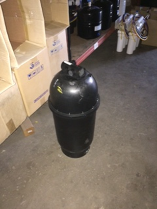
Water Boss resin tank $13.50 plus tax
new resin $86.25 plus tax (0.69 cubic feet cation resin)
This is an image taken from the bag of resin that we sell. We utilize this same resin when building our rental water softeners.
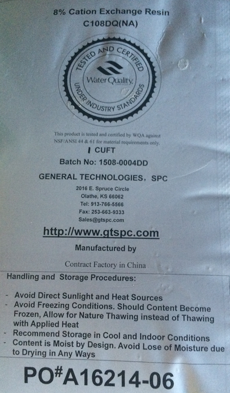
07.05.15 12:03 PM
#16
Premier Model AF-40K Water Softening System. This unit is purchased at Cost Co (Cost Co Water Softener). This is a small capacity Cost Co water softener (this water softener contains only 40,000 grains of cation resin media). It may not operate effectively in Arizona. If you use this water softener to soften the water for the clothes washer (based upon our scientific data) your water may not be completely soft. Our company plans to provide parts and service for this unit.
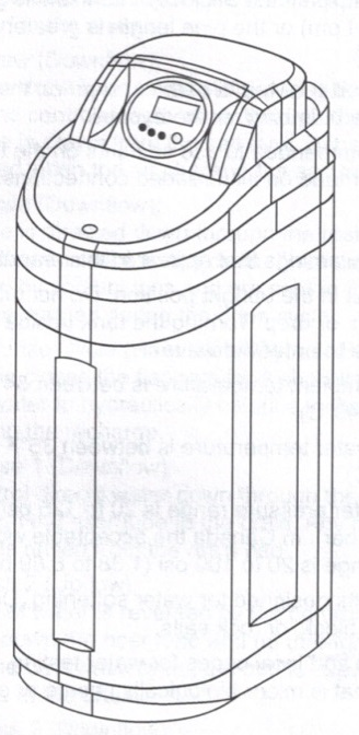
Tank Assembly for the Premier Model AF-40K Water Softening System
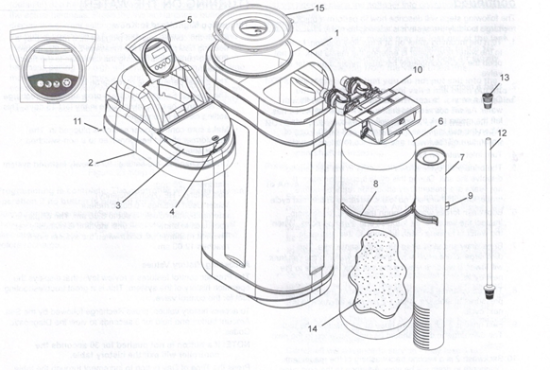
Item QTY Part Description
1 1 367023 Tank Brine
2 1 213126 Housing
3 1 313012 Lid
4 1 367202 Latch
5 1 167028 Controller, AF-40K
6 1 367026 Resin Tank
7 1 367203 Brine Tube Assembly
8 1 249033 Clamp, Resin Tank
9 1 249035 Clamp, Float Tube
10 1 116181 Valve Assembly w/Bypassand Connectors
11 6 246068 Housing Mounting Screws
12 1 367204 Lower Distributor Assembly10x35 Tank
13 1 367205 Upper Basket
14 1 367206 Conditioning Resin
15 1 367207 Retainer, Brine Tank
Valve Assembly for the Premier Model AF-40K Water Softening System
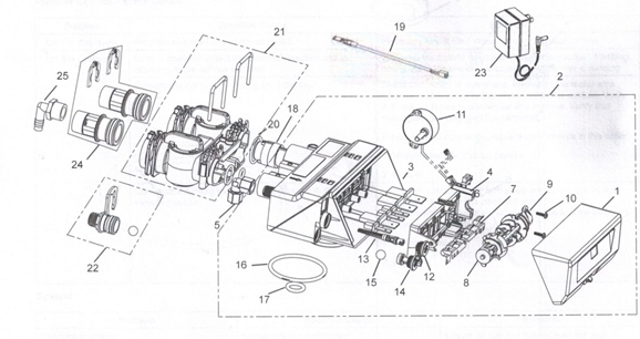
Item No. QTY Part No. Description
1 1 367208 Assembly, Premier ControllerCover
2 1 116182 Valve Body Assy, VolumetricIncludes Item #18
3 1 367209 Valve Disc Kit
4 1 367210 Top Plate
5 I 125139 Female Elbow, 3/8 NPT to3/8 Tubing
6 1 2146034 Screw, Top Plate
7 1 367211 Spring, Top Plate
8 1 367212 Camshaft, Refill First –
9 1 367213 Yoke, Camshaft
10 2 146036 Screw, Yoke
11 I 270341 368 Valve Motor/OpticalSensor Assy
12 1 367214 Injector Cap Assembly
13 1 367215 “J” Injector, Lt Blue, 10 Inch Tank
…………….1 367216 Screen
…………….1 367217 “J” Injector w/0-rings
Item No. QTY Part No. Description
14 1 622013 Assembly, Refill Cont, .33gpm
15 2 622014 Ball, Backwash, Brine RefillController
16 1 252229 O-ring,Tank
17 1 252230 0-ring, Riser
18 1 367218 MeterAssembly
19 1 258261 Assembly, Sensor Cable
20 1 252231 Kit, 0-ring, Manifold
21 1 116183 Bypass
………….1 367224 Main Assembly
…………2 367219 Retainer, Manifold
………….2 228305 Clips Retainer
………….1 252232 Kit, 0-ring Manifold
22 1 622015 Kit, Drain Line Flow Control
…………..1 622016 Flow Control w/0-ring andClip Drain Line and Ball
23 1 258100 12O VAC, 6O Hz, N. America Plug
24 2 125154 Connector Assembly, 1″ NPT, Plastic, w/ 0-ring and Clip
…Retainer
25 1 125155 Fitting, Drain Line, 90°, 1/2″ NPT, 1/2″ Tube
BRINE WELL ASSEMBLY CH20795
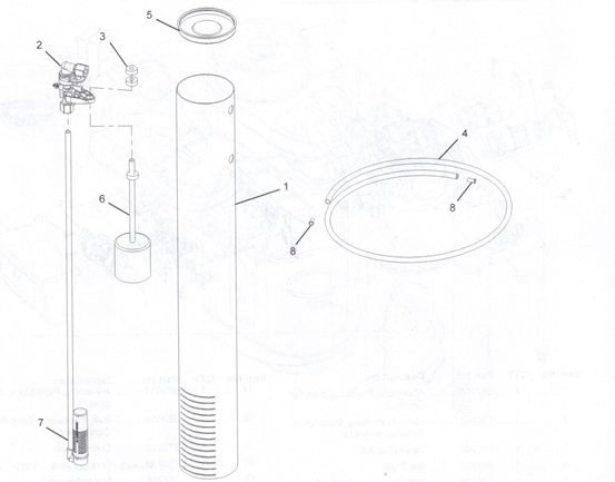
Item No. QTY Part No. Description
1 1 367220 Brine Well w/Slots
2 1 116184 Safety Brine Valve
3 2 228306 Grommet
4 1 400080 Tubing, 3/8 x 16″ Long
5 1 367221 Cap, Brine Well 4″ Dia. (Caplug STP-4)
6 1 367222 Brine Float w/One Grommet (As purchased)
7 1 367223 Air Check Assembly
8 2 231049 Tubing Insert, Brass
Not Shown
……………..1 231056 Overflow Fitting Assembly
………………1 *231057 Overflow Elbow
……………..1 *231058 Overflow Nut
……………..1 *252234 Gasket
*Parts included with CH20774 Overflow Fitting Assembly
TROUBLESHOOTING
Premier Control – Error Codes
Problem Possible Cause Solution
If Err 1 is displayed. Program settings have been corrupted.Press any key. If Err 1 does not clear, replace control.
If Err 3 is displayed.Control does not detect the camshaft position and is returning to the service position,Wait until the control returns to the service position. Flashing hourglass in the display indicates that the motor is running
Camshaft is not turning during Err 3 display.Check that motor is connected. Verify that the motor wire harness is connected to motor and controller module. Verify that optical sensor is connected and in place. Verify that motor gear has engaged the camshaft.
If everything is connected, replace components in this order:
- Motor Assembly, Optical Sensor
- Control
Camshaft is turning more than five minutes to find the service position: Verify that optical sensor is in place and connected to wire. Inspect for debris in the camshaft slots. If motor continues to rotate indefinitely, replace the following components in this order:
- Optical Sensor
- Control
System
Salt tank overflow. Loose salt line connection. Ensure all salt line connections are tight.
Drain line restricted with debris. Clean drain control.
Flowing or dripping water at drain or salt line after recharge. Debris is preventing #4 valve disc from closing (Figure 23 Valve Layout). Remove debris.
Worn #4 valve disc (Figure 23 Valve Layout). Replace valve discs.
Hard water leakage after recharge. Improper recharge. Repeat recharge after making certain correct salt dosage was set.
Leaking of external bypass valve.Replace bypass valve.
0-Ring around riser pipe damaged. Replace 0-ring.
Valve will not draw brine. Restricted drain line. Remove restriction.
Injector plugged. Clean injector and screen.
Debris preventing valve discs from closing. Remove foreign matter from valve discs.
Control will not recharge automatically. AC adapter or motor not connected. Connect power.
Defective motor. Replace motor.
Meter clogged with debris. Unit will recharge every 7 days anyway. Remove and clean meter.
Control recharges at wrong time of day. Time of Day set incorrectly. Set the correct Time of Day.
Intermittent salt draw. Low water pressure. Maintain a minimum of 20 psi (1.3 bar) feed.
No conditioned water after recharge. No salt in salt tank. Add salt to salt tank.
Injector plugged. Clean injector and screen.
Backwashes or rinses at excessively low or high rate. No drain line flow control. Install drain line flow control.
Restricted drain line. Remove restriction.
Runs out of conditioned water between recharges. Control improperly programmed. Verify salt dosage.
Flow indicator on control does not display service flow. Bypass valve in bypass position. Remove bypass valve from bypass. Meter cable dislodged from valve. Fully insert meter cable into valve.
Meter clogged with debris. Remove and clean meter.
TROUBLESHOOTING continued Valve Disc Operation
When the Premier control is lifted up (Figure 22 Control Removed) and the cover is removed, the flappers and camshaft are visible (Figure 23 Valve Layout).
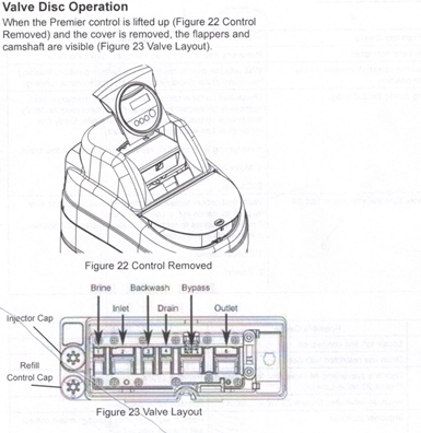
Premier Model AF-40K Water Softening System. This unit is purchased at Cost Co (Cost Co Water Softener). This is a small capacity Cost Co water softener (this water softener contains only 40,000 grains of cation resin media) . Will this Cost Co water softener effectively soften the water in Arizona for a single family home? No. Why? Because it does not contain 64,000 grains of capacity (of cation resin). 64,000 grains of cation resin is the minimum capacity in order to effectively soften the water for a clothes washing machine. We are members of Cost Co (we have been loyal members for many years). We purchased this water softener so we can be ready to help you when you need service. We have experience connecting this unit and we have explicated the inner working parts. We don’t think this unit is efficient and we have concerns about the operating parameters (based upon the limited capacity ‘it contains only 40,000 grains of cation resin’ – it will not effectively soften the water for a clothes washer). However, we wish to adopt orphans who need service on this unit.
The purpose of this picture story is to show you the process that our company has developed to rebuild your water softener.
Our technician arrives at your home.
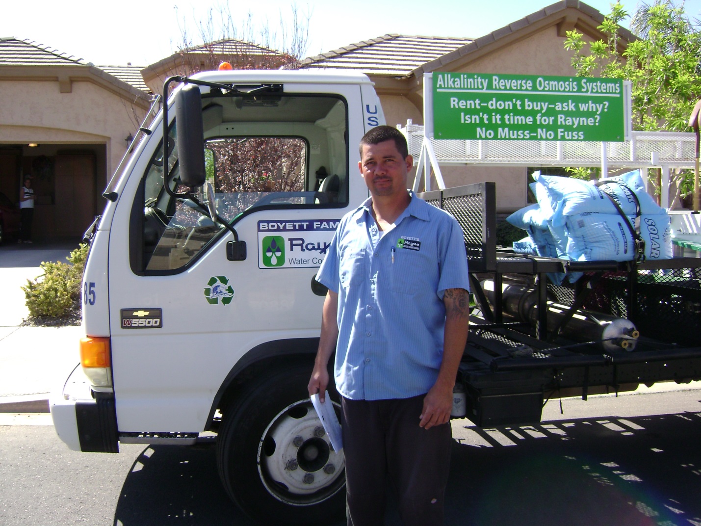
This is Brett; he has worked in our firm for at least 13 years.
The next step is; we explain to our customers in great detail the processes in which we will be performing on their home.

This is Brett explaining to Suzanne the work he will perform on her water softener. Brett will be removing the water softener from her home and bringing her unit to our factory for a complete rebuild. Brett explains to Suzanne the next step he will perform is to turn off the water to her home, but before turning off the water he will check the water pressure in her home.
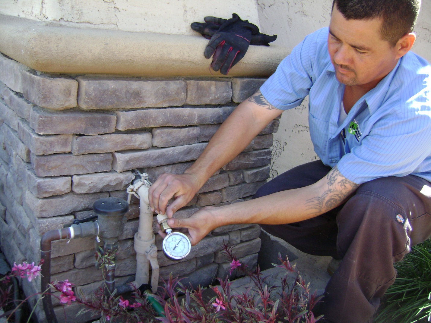
Brett is checking the water pressure in Suzanne’s home. We always inform our clients to keep their water pressure regulated to 70 PSI or less.
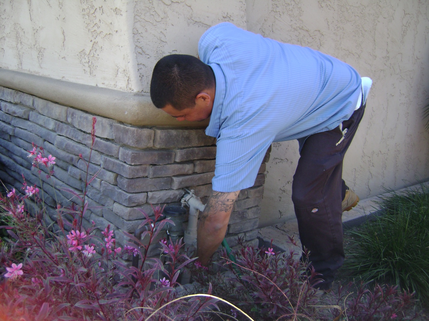
Brett turning off the water to Suzanne’s home.
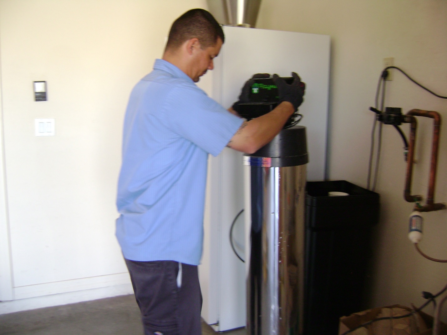
Brett removes the water softener from Suzanne’s home to bring back to our office for a complete rebuild.

We also bring the brine tank into our office to clean it.
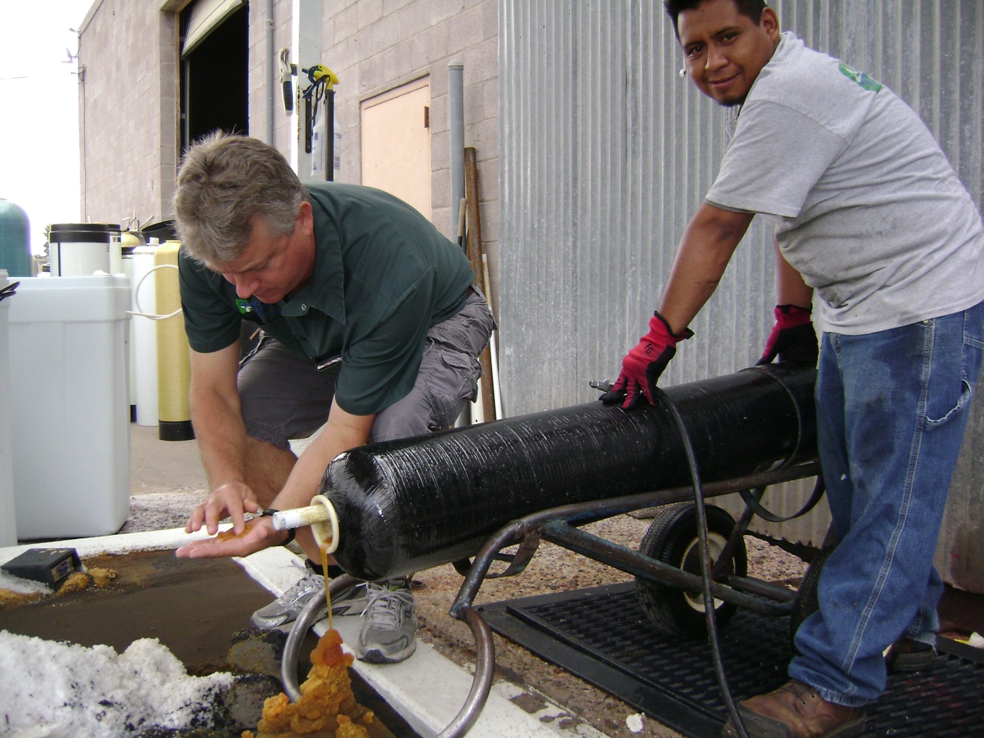
This is Troy and Sabatian emptying the cation resin into our work area.
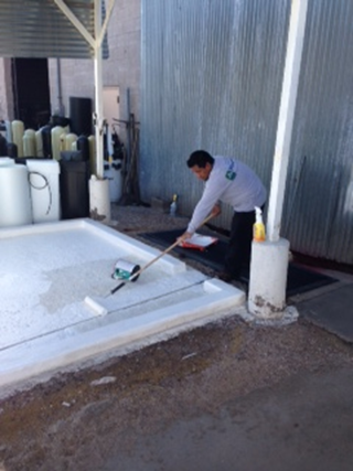
This is how this area looks when it is completely clean.
This is Sabastian painting this area on 031715 8:51 AM. We like to keep our work areas clean and sanitary.
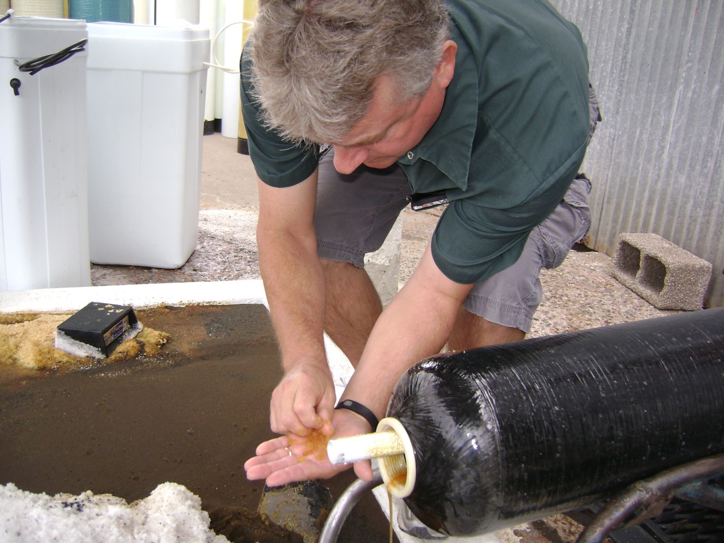
This is Troy Phillips (our service manager) inspecting the cation resin. We have made this a scientific experiment since February 18, 2010.

Because the water treatment plants add so much chlorine to the water; the cation resin is lasting only 5 years in the Phoenix metro area. In order to sustain great soft water; some action must be taken to change the resin every five years. Our onus is to become valley leaders ‘keeping the cation resin sustainable’ in your water softener.
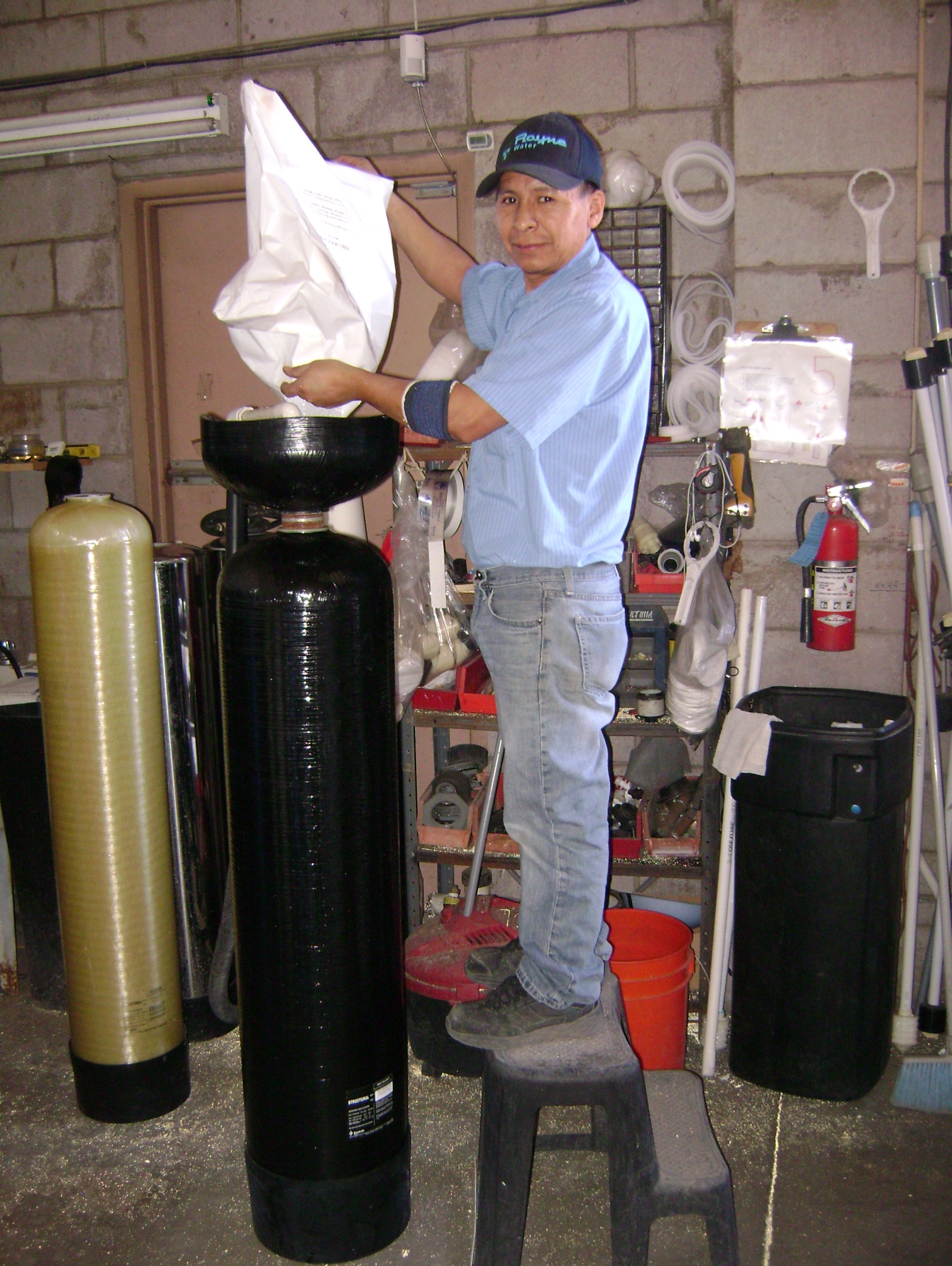
This is Fancisco adding 8% cross linked resin into your resin tank. We purchase the best components to add to your water softener. Here is a link which we explicate and describe the cation resin we utilize in our water softener rebuilding process: http://wp.azh2o.com/faq/
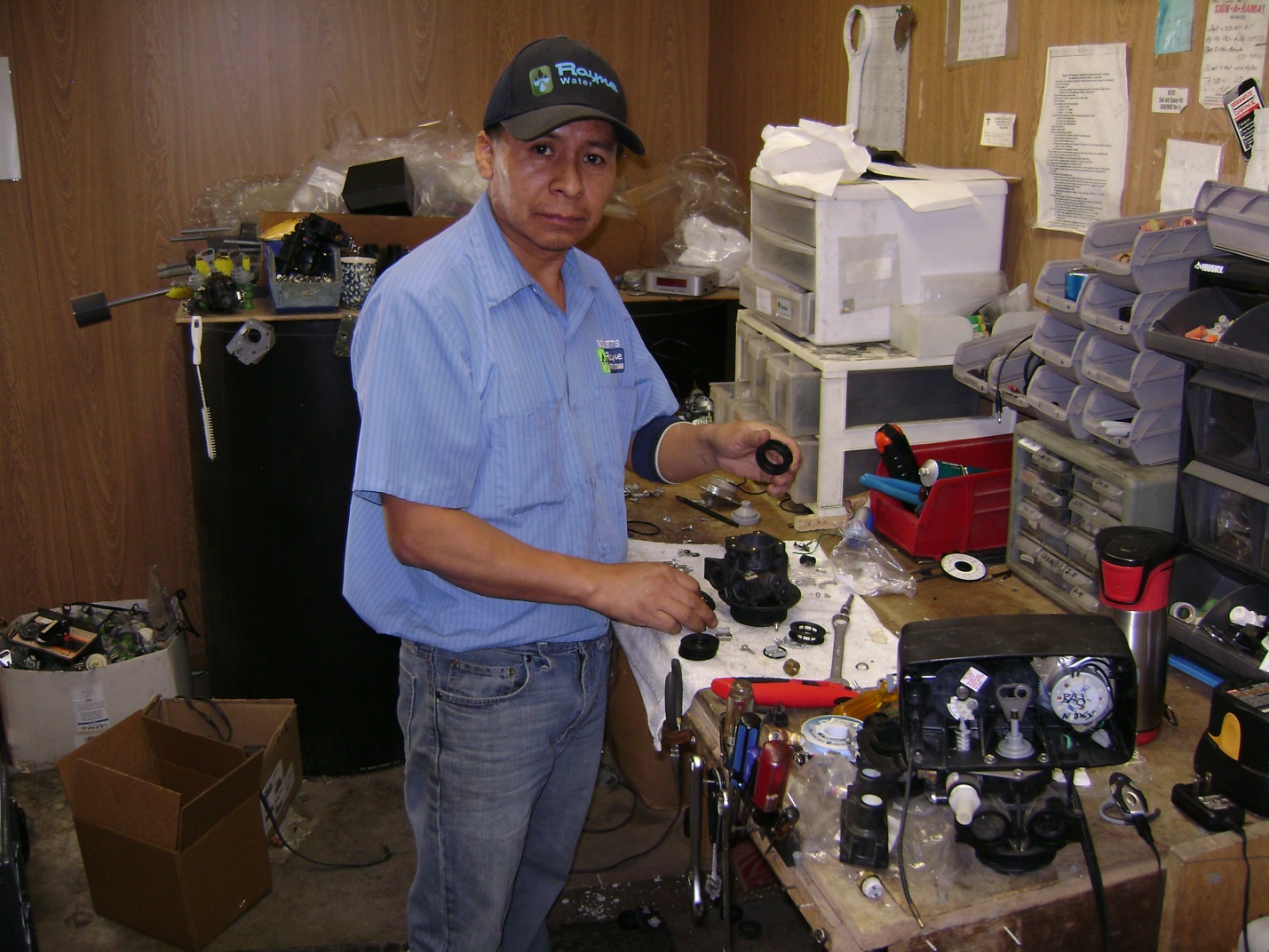
Francisco removes all the o rings, inductors, injectors, seals, piston and motor and he puts new components into your water softener valve. We call this rebuilding your water softener valve. There are as many as 20 different sized o rings in each valve. All of these components are exposed to the chlorine. The chlorine disintegrates these component parts.
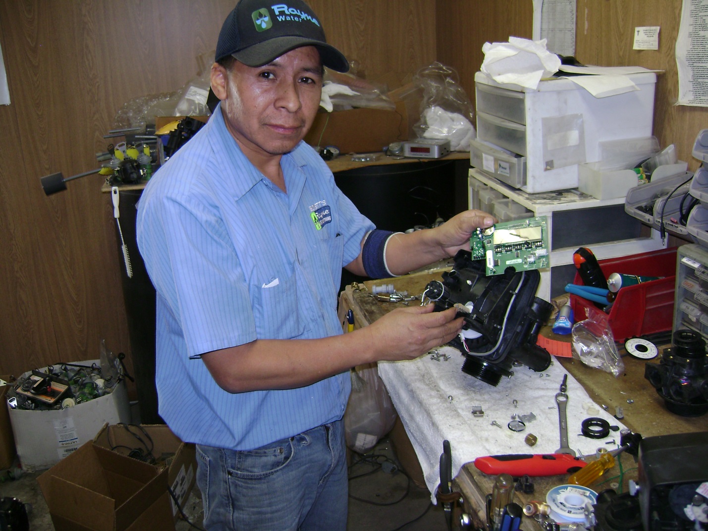
When this water softener rebuilding process is complete, and the unit passes our quality standards, we return the water softener to Suzanne’s home.
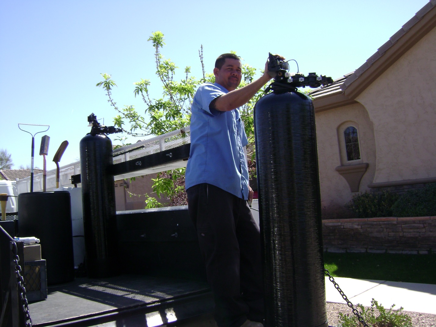
And reconnect this unit.
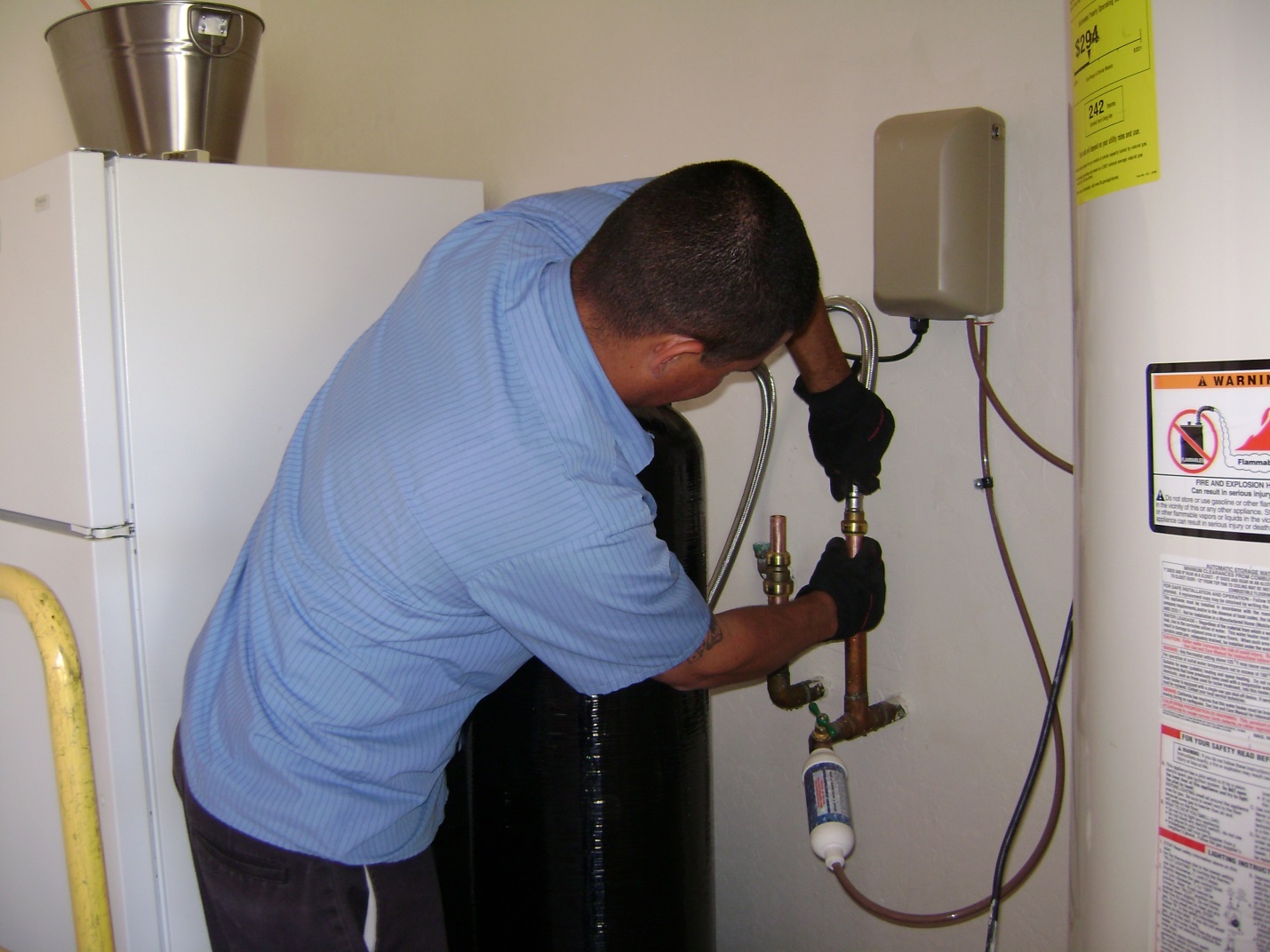

When we return the water softener we always deliver two bags of salt.
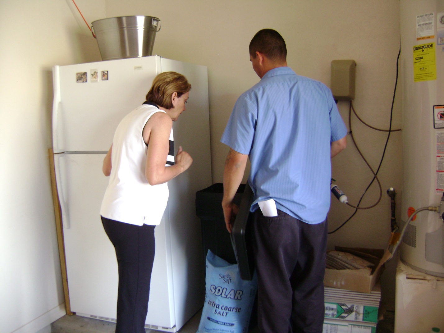
Brett is explaining to Suzanne the service we performed on her rebuilt water softener and her responsibilities to maintain this water softener.
We can rebuild your water softener. Please call our office for details (480) 969-7251 or e-mail me This email address is being protected from spambots. You need JavaScript enabled to view it.. If you would like parts and information to perform this rebuild process – we are glad to help.
09.22.15 6:18 PM
Whirlpool
Model WHES40
Model WHES44
Model WHESCS
Water softener
Installation and operation manual *
How to install, operate
and maintain your Demand
Controlled Water Softener

Our industry refers to this unit configuration as a tank in tank unit. In Arizona the salt can stick to the resin tank. We call this problem a ‘salt bridge’. Salt bridges are very inconvenient.
Specifications & Performance Claims
These models are efficiency rated. The efficiency rating is valid only at the minimum salt dose and rated service flow. These softeners have a demand initiated regeneration (D.l.R.) feature that complies with specific performance specifications intended to minimize the amount of regenerant brine and water used in their operation.
These softeners have a rated softener efficiency of not less than 3,350 grains of total hardness exchange per pound of salt (based on sodium chloride) and shall not deliver more salt than their listed rating or be operated at a sustained maximum service flow rate greater than their listed rating. These softeners have been proven to deliver soft water for at least ten continuous minutes at the rated service flow rate. The rated salt efficiency is measured by laboratory tests described in NSF/ANSI Standard 44. These tests represent the maximum possible efficiency that the system can achieve. Operational efficiency is the actual efficiency after the system has been installed. It is typically less than the rated efficiency, due to individual application factors including water hardness, water usage, and other contaminants that reduce a softener’s capacity.
Model WHES40 Model WHES44
Model Code LL40 LL44
Packing List

Bypass valve, Drain Hose, Clips, installation adapters, Hose Clamps, Adapter Elbow, Grommet, 0-rings , Water Hardness Test Strip
Water Conditioning Information
IRON
Iron in water can cause stains on clothing and plumbing fixtures. It can negatively affect the taste of food, drinking water, and other beverages. Iron in water is measured in parts per million (ppm). The total* ppm of iron, and type or types*, is determined by chemical analysis. Four different types of iron in water are:
- Ferrous (clear water) iron
- Ferric (red water) iron
- Bacterial and organically bound iron
- Colloidal and inorganically bound iron (ferrous or ferric)
Ferrous (clear water) iron is soluble and dissolves in water. This water softener will reduce moderate amounts of this type of iron (see specifications).** Ferrous (clear water) iron is usually detected by taking a sample of water in a clear bottle or glass. Immediately after taking, the sample is clear. As the water sample stands, it gradually clouds and turns slightly yellow or brown as air oxidizes the iron. This usually occurs in 15 to 30 minutes.
When using the softener to reduce Ferrous (clear water) iron, add 5 grains to the hardness setting for every I ppm of Ferrous (clear water) iron. See “Set Water Hardness Number” section.
Ferric (red water), and bacterial and organically bound irons are insoluble. This water softener will not remove ferric or bacterial iron. This iron is visible
immediately when drawn from a faucet because it has oxidized before reaching the home. It appears as small cloudy yellow, orange, or reddish suspended particles. After the water stands for a period of time, the particles settle to the bottom of the container. Generally these irons are removed from water by filtration. Chlorination is also recommended for bacterial iron.
Colloidal and inorganically bound iron is of ferric or ferrous form that will not filter or exchange out of water. This water softener will not remove colloidal iron. In some instances, treatment may improve colloidal iron water. Colloidal iron water usually has a yellow appearance when drawn. After standing for several hours, the color persists and the iron does not settle, but remains suspended in the water.
SEDIMENT
Sediment is fine, foreign material particles suspended in water. This water softener will not remove sediment. This material is most often clay or silt. Extreme amounts of sediment may give the water a cloudy appearance. A sediment filter installed upstream of the water softener normally corrects this situation.
* Water may contain one or more of the four types of iron and any combination of these. Total iron is the sum of the contents.
** Capacity to reduce clear water iron is substantiated by WQA test data.
Programming the Water Softener

Words in picture: SET SALT LEVEL, Display, UP button, TANK LIGht button, STATUS LIGHT (see below), RECHARGE button, DOWN button, PROGRAM button, STATUS LIGHT, PROGRAM THE SOFTENER fig 15
When the water softener is connected to electrical power, the status light on the control panel will operate as follows:
- Light flashing slowly, along with the salt level indicators in the display – The salt monitor system indicates a low salt level and needs to be set See “Set Salt Level” on Page 14.
- Light flashing slowly, along with the words “SCHEDULED CLEAN” in the display – Four months have elapsed on the system’s timer since start up or the last reset. This is a reminder to use Whirlpool® WHE-WSC Water Softener Cleanser three times a year. To reset the timer, press any button on the control panel and the flashing words will disappear. The status light will stop flashing, unless the system is also low on salt (see above).
- Light flashing rapidly, with “CURRENT TIME” shown in the display and the clock flashing slowly – The present time needs to be set, either during initial start up or after a long power outage. See “Set Time of Day”, at right.
- Light flashing rapidly, with “Err” shown in the display – The electronic self-diagnostics have detected a problem. See “Troubleshooting” on Page 18.
- Light on steady (not flashing) – The system has power applied and does not require any attention.
When the power supply is plugged into the electrical outlet, the model code (“LL40” for Model WHES40 or “LL44” for Model WHES44) and a test number (example: J3.0), are briefly shown in the display. Then the words “CURRENT TIME” appear and 12:00 PM begins to flash.
SET TIME OF DAY
If the words “CURRENT TIME” do not show in the
display, press the PROGRAM button until they do.
- Press the UP or DOWN buttons to set the present time. Up moves the display ahead; down sets the time back. Be sure AM or PM is correct.
NOTE: Press buttons and quickly release to slowly advance the display. Hold the buttons down for fast advance.
Programming the Water Softener
SET WATER HARDNESS NUMBER
- Press the PROGRAM button once again to display a flashing “25” and the word “HARDNESS”.
- Press the UP or DOWN buttons to set your water’s hardness number.
NOTE: If your water supply contains iron, compensate for it by adding to the water hardness number. For example, assume your water is 20 gpg hard and contains 2 ppm iron. Add 5 to the hardness number for each I ppm of iron. In this example, you would use 30 for your hardness number.
20 gpg hardness
2ppm iron x 5 = + I0
30 HARDNESS NUMBER
SET RECHARGE (REGENERATION) TIME
- Press the PROGRAM button once again to display
a flashing “2:00AM” and the words “RECHARGE
TIME”. This is a good time for the recharge to start
in most households, because water is not in use.
- If you want to change the recharge start time, press the UP or DOWN buttons until the desired time shows. Be sure AM or PM is correct.
SET SALT TYPE
- Press the PROGRAM button once again to display a flashing “nACL”.
Salt Type allows you to choose between sodium chloride (NaCI), which is regular softener salt, or potassium chloride (KCI), which is an alternative to sodium chloride. KCI (potassium chloride) may be used if the user of the water softener is on a sodium restricted diet and is concerned about the amount of sodium in the water supply.
KCI should be used in accordance with the following steps to help give you years of maintenance free service.
Place only one bag at a time of KCI into your softener (the salt storage tank should contain no more than 60 pounds of KCI at any one time).
NOTE: A softener using KCI should not be located in areas with high temperature changes or high humidity (KCI may harden in these environments and make the softener inoperable).
- Check the brine tank and brinewell (black tube in salt storage tank) monthly. If hardening is present, pour small amounts of warm water on hardened areas until they loosen.
- Be sure to set the correct salt type, depending on which type of salt is used (Na Cl or KCI). Use the UP or DOWN buttons to toggle between NaCl and KCI, then press the PROGRAM button to enter the selection.
- Press the PROGRAM button once again to return to normal operating display.
START A RECHARGE
- Press the RECHARGE button and hold for three seconds, until “RECHARGE” begins to flash in the display, starting a recharge. This recharge draws the sanitizing bleach into and through the water softener. Any air remaining in the water softener is purged to the drain. During this time, periodically check for leaks.
NOTE: As with all other water system applications, leaks may occur. Leaks may not be immediately apparent. Recheck for leaks 24 hours after first recharge cycle is complete.
Customizing Features / Options
RECHARGE
The RECHARGE button is used to initiate an immediate recharge.
- Press and hold the RECHARGE button until the words “RECHARGE”, “SERVICE” and “FILL” flash
in the display.
Recharge initiated
The softener enters the fill cycle of regeneration right away. “RECHARGE” will flash during the regeneration. When completed, full water conditioning capacity is restored. While water softener is running a recharge, the time remaining until the recharge is completed will show in the display during all cycles except for the Fill cycle.
NOTE: Avoid using hot water while the softener is regenerating, because the water heater will refill with bypass hard water.
RECHARGE SCHEDULED
If you do not want to start an immediate recharge, but would like to schedule an extra recharge at the next preset recharge time, do the following:
- Press and release (do not hold) the RECHARGE button.
RECHARGE scheduled
The words “RECHARGE SCHEDULED” flash in the display, and the softener will recharge at the next recharge time. The word “RECHARGE” will flash during the regeneration. When completed, full water conditioning capacity is restored.
SET SALT LEVEL
The water softener has a salt monitor indicator light to
remind you to add salt to the storage tank.
NOTE: You must set salt level each time salt is added
to the water softener.
To set this monitor system:
- Lift the salt lid and level the salt in the storage tank.
- The salt level scale, on the brinewell inside the tank, has numbers from 0 to 8. Observe the highest number the leveled salt is at, or closest to.
- Press the SET SALT LEVEL button until black ovals correspond to the salt level number (See Figure 22). At level 2 or below, the “Check Salt Level” LED indicator will flash.
If you want to turn the salt monitor off, press the SET SALT LEVEL button until “SALT LEVEL OFF” shows in the display
TANK LIGHT
The water softener is equipped with a tank light for viewing the salt level in the brine tank. Push the tank light button on the electronic control once, and the tank light will turn on. Pushing the tank light button again will turn the light off. The tank light will automatically turn off after a period of 15 minutes if the tank light button is not used to turn it off.
Customizing Features I Options
POWER OUTAGE MEMORY
If electrical power to the water softener is lost, “memory” built into the timer circuitry will keep all settings for several hours. While the power is out, the display is blank and the water softener will not regenerate. When electrical power is restored, the following will occur:
Reset the present time only if the display is flashing. The HARDNESS and RECHARGE TIME never require resetting unless a change is desired. Even if the clock is incorrect after a long power outage, the softener operates as it should to keep your water soft. However, regenerations may occur at the wrong time of day until you reset the clock to the correct time of day.
NOTE: If the water softener was regenerating when power was lost, it will now finish the cycle.
WATER FLOW INDICATOR
Whenever the softener has water flowing from the outlet port, the display will show water droplets scrolling down the right hand side of the screen (See Figure 24). The faster the water flow, the faster the droplets will flash.
SALT EFFICIENCY
When this feature is ON, the water softener will operate at salt efficiencies of 4000 grains of hardness per pound of salt or higher (May recharge more often using smaller salt dosage and less water). The softener is shipped with this feature set OFF.
- Press and hold the PROGRAM button until the screen in Figure 25 is displayed. Once in this display, press the PROGRAM button once and one of the two displays in Figure 26 is shown.
- Press the UP or DOWN buttons to set ON or OFF. When set to ON, the efficiency icon will be displayed in the lower left hand corner of the normal run display.
- Press the PROGRAM button five times to return to the normal run display.
09.23.15 1:40 PM
CLEAN FEATURE MINUTES
The Clean I Clear Water Iron Reduction feature (described above) may be adjusted, from I to 15 minutes in length. To change this cycle time, use the UP button to increase the time, or the DOWN button to shorten the time. The default value for this feature is 2 minutes.
- Press and hold the PROGRAM button. Once in 000 is in the display, press the PROGRAM button three times and the display will show 2.
- Press the UP or DOWN buttons to set the number of minutes.
- Press the PROGRAM button three times to return to the normal run display.
MAXIMUM DAYS BETWEEN REGENERATIONS
The water softener automatically controls regeneration frequency. This provides the greatest operating efficiency and, under most conditions, this feature should be left in this automatic mode. However, you may modify this feature if you want to force a regeneration every set number of days. For example, if your water supply contains clear water iron, you may want the softener to regenerate every few days to keep the resin bed clean. The maximum days between recharges may be set from I to 15 days, as follows:
NOTE: The softener will recharge on its own if needed, even if it is before the set number of days.
- Press and hold the PROGRAM button until the
screen displays 000 . Once in this dis-
play, press the PROGRAM button four times and
the display will show —- .
- Press the UP or DOWN buttons to set the number of days.
- Press the PROGRAM button two times to return to the normal time of day screen.
12 OR 24 HOUR CLOCK
All time displays are shown in standard clock time (AM and PM) at the 12 hour default setting. If 24 hour clock displays are desired, follow steps below:
- Press and hold the PROGRAM button until the screen displays 000. Once in this display, press the PROGRAM button five times and one of the these two figures will appear 12hr or 24hr.
- Press the UP or DOWN buttons to set the time format.
- Press the PROGRAM button once again, to return to the normal time of day screen.
Routine Maintenance
ADDING SALT
Lift the salt lid and check the salt storage level frequently. If the water softener uses all the salt before you refill it, you will experience hard water. Until you have established a refilling routine, check the salt every two or three weeks. Always add if less than 1/4 full. Be sure the brinewell cover is on.
NOTE: If using potassium chloride (KCl), do not fill
above level 4 on the brinewell scale.
NOTE: In humid areas, it is best to keep the salt storage level lower, and to refill more often to avoid salt “bridging”.
Recommended Salt: Nugget, pellet or coarse solar salts with less than 1% impurities.
Salt Not Recommended: Rock salt, high in impurities, block, granulated, table, ice melting, ice cream making salts, etc.
BREAKING A SALT BRIDGE
Sometimes, a hard crust or salt “bridge” forms in the brine tank. It is usually caused by high humidity or the wrong kind of salt. When the salt “bridges,” an empty space forms between the water and the salt. Then, salt will not dissolve in the water to make brine. Without brine, the resin bed is not recharged and hard water will result.
If the storage tank is full of salt, it is difficult to tell if you have a salt bridge. A bridge may be underneath loose salt. Take a broom handle, or like tool, and hold it next to the water softener. Measure the distance from the floor to the rim of the water softener. Then, gently push the broom handle straight down into the salt If a hard object is felt before the pencil mark is even with the top, it is most likely a salt bridge. Gently push into the bridge in several places to break it. Do not use any sharp or pointed objects as you may puncture the brine tank. Do not try to break the salt bridge by pounding on the outside of the salt tank. You may damage the tank.

Words in the picture: Push Tool into; Salt Bridge to; Break; Pencil Mark; Broom Handle
CLEANING THE NOZZLE & VENTURI
A clean nozzle & venturi (See Figure 33) is a necessity for the water softener to work properly. This small component creates the suction to move brine from the brine tank, into the resin tank. If it should become plugged with sand, silt, dirt, etc., the water softener will not work, and hard water will result.

Words in picture: 0-ring Seal; Screen Support; Screen; Nozzle & Venturi Disc; Plug; Gasket; Cone Screen; Flow Plug (HVDC) ;Housing; Ferrule
*Install with lettered side up, concave Nut side down.
IMPORTANT: Be sure small hole in the gasket is centered directly over the small hole in the nozzle & venturi housing. Be sure the numbers are facing up
To get access to the nozzle & venturi, remove the water softener’s top cover. Put the bypass valve(s) into the bypass position. Be sure the water softener is in soft water (service) cycle (no water pressure at nozzle & venturi). Then, holding the nozzle & venturi housing with one hand, unscrew the cap. Do not lose the 0-ring seal. Lift out the screen support and screen. Then, remove the nozzle & venturi disc, gasket and flow plug(s). Wash the parts in warm, soapy water and rinse in fresh water. Be sure to clean both the top and bottom of the nozzle & venturi disc. If needed, use a small brush to remove iron or dirt. Do not scratch, misshape, etc., surfaces of the nozzle & venturi.
Gently replace all parts in the correct order. Lubricate the 0-ring seal with silicone grease and locate in place. Install and tighten the cap by hand, while supporting the housing. Overtightening may break the cap or housing. Put the bypass valve(s) into service (soft water) position.
Recharge the softener to reduce water level in the tank. This will also assure that the softener is completely recharged and ready to provide softened water again. Check the water level in the tank by looking down the brinewell. If the water level does not drop after a recharge, the problem has not been resolved. Call 1-(480) 969-7251, Monday – Friday, 8 am to 5 PM Mountain Time.
Troubleshooting
AUTOMATIC ELECTRONIC DIAGNOSTICS
This water softener has a self-diagnostic function for the electrical system (except input power and/or water meter). The water softener monitors electronic components and circuits for correct operation. If a malfunction occurs, an error code appears in the display.

Err I
While an error code appears in the display, all buttons are inoperable except the PROGRAM button. PROGRAM remains operational so the service person can perform the Manual Advance Diagnostics, see below, to further isolate the problem.
Procedure for removing error code from display:
- Unplug power supply from electrical outlet.
- Correct problem.
- Plug power supply back in.
- Wait 8 minutes. The error code will return if the problem was not corrected.
MANUAL ADVANCE DIAGNOSTICS
Use the following procedures to advance the water softener through the regeneration cycles to check operation.
Lift off the salt lid, remove the top cover by unlocking the tabs in the back and rocking forward, to observe cam and switch operation during valve rotation.
- Press and hold PROGRAM for 3 seconds until “000” shows in the display, then release.
- The 3 digits indicate water meter operation as follows:
000 (steady) = Soft water not in use, and no flow
through the meter.
Open a nearby soft water faucet.
000 to 140 (continual) = Repeats for each gallon of water passing through the meter.
- Symbols in the display indicate POSITION switch operation
Switch is open (Cam not rotating) Switch is closed (Cam rotating)
- Use the RECHARGE button to manually advance the valve into each cycle and check correct switch operation.
NOTE: Be sure water is in contact with the salt, and not separated by a salt bridge (See “Breaking A Salt Bridge” section).
- While in this diagnostic screen, the following information is available and may be beneficial for various reasons. This information is retained by the computer from the first time electrical power is applied to the electronic controller.
- Press the UP button to display the number of days this electronic control has had electrical power applied.
- Press the DOWN button to display the number of regenerations initiated by this electronic control since the code number was entered.
- Press and hold the PROGRAM button until the model code (“LL40” for Model WHES40 or “LL44” for Model WHES44) shows in the display. This code identifies the softener model. If an incorrect model code is displayed, the softener will operate on incorrect configuration data.
- To change the code number, press the UP or V DOWN button until the correct code shows.
- To return to the present time display, press the PROGRAM button.
Troubleshooting
RESETTING TO FACTORY DEFAULTS
To reset the electronic controller to its factory default for all settings (time, hardness, etc.):
- Press the PROGRAM button and hold it until the display changes twice to show the flashing model code.
- Press the UP button (a few times, if necessary) to display a flashing “SoS”.

- Press the PROGRAM button, and the electronic controller will restart.
- Set the present time, hardness, etc., as described
MANUAL ADVANCE REGENERATION CHECK
This check verifies proper operation of the valve motor, brine tank fill, brine draw, regeneration flow rates, and other controller functions. Always make the initial checks, and the manual initiated diagnostics.
NOTE: The electronic control display must show a steady time (not flashing). If an error code shows, first press the PROGRAM button to enter the diagnostic display.
- Press the RECHARGE button and hold in for 3 seconds. RECHARGE begins to flash as the softener’s valve advances from the service to fill position. Remove the brinewell cover and, using a flashlight, observe fill water entering the tank.
If water does not enter the tank, look for an obstructed nozzle, venturi, fill flow plug, brine tubing, or brine valve riser pipe.
- After observing fill, press the RECHARGE button to move the softener’s valve into the brine position. A slow flow of water to the drain will begin. Verify brine draw from the brine tank by shining a flashlight into the brinewell and observing a noticeable drop in the liquid level. This may take 15 to 20 minutes.
NOTE: Be sure water is in contact with the salt, and not separated by a salt bridge (See “Breaking A Salt Bridge” section).
If the water softener does not draw brine, check for (most likely to least likely):
- Dirty or plugged nozzle and venturi, see “Cleaning the Nozzle and Venturi” section.
- Nozzle and venturi not seated on the gasket, or gasket deformed.
- Valve seals leaking (See Troubleshooting).
- Restriction in valve drain, causing a back-pressure (bends, kinks, elevated too high, etc.). See “Install Valve Drain Hose” section.
- Obstruction in brine valve or brine tubing.
NOTE: If water system pressure is low, a too-long or elevated drain hose may cause back pressure, stopping brine draw. Avoid drain hose runs longer than 30 feet. Avoid elevating the hose more than 8 feet above the floor.
- Press the RECHARGE button to move the softener’s valve into the backwash position. Look for a fast flow of water from the drain hose. Check that the drain can adequately handle the flow and volume.
An obstructed flow indicates a plugged top distributor, backwash flow plug, or drain hose.
- Press the RECHARGE button to move the softener’s valve into the fast rinse position. Again look for a fast drain flow. Allow the softener to rinse for a few minutes to flush out any brine that may remain in the resin tank from the brining cycle test.
- To return the softener’s valve to the service position, press the RECHARGE button.
Softener Exploded View

Softener Parts List
Key No Part No. Description
– 7112963 Distributor 0-Ring Kit (includes Key Nos. 1-3)
I same 0-Ring, 2-7/8″ x 3-1/4″
2 same 0-Ring, 13/16″ x 1-1/16″
3 same 0-Ring, 2-3/4″ x 3″
4 7077870 Top Distributor
5 7105047 RepI. Bottom Distributor
– 7331177 Tank Neck Clamp Kit (includes 2 ea. of Key Nos. 6 & 7)
6 same Clamp Section (2 req.)
7 same Retainer Clip (2 req.)
7161849 RepI. Resin Tank, 9″ x 40″, Model WHES40
8
7247996 RepI. Resin Tank, 10″ x 40″,Model WHES44
9 0502272 Resin, I Cu. ft.
10 7310202 Repl. Brine Valve Assembly
11 7327568 Float, Stem & Guide Assembly
12 7337482 Power Supply, 28V DC
13 7335163 RepI. Electronic Control Board (PWA)
14 7267116 Top Cover & Faceplate Assembly, (order decal below)
7335553 Faceplate Decal
Key No. Part No. Description
15 7262661 Salt Lid (order decal below)
7336622 Instruction Decal
16 7262768 Rim
17 7335901 Cover, Brinewell
18 7137824 Brinewell Assembly (including salt level decal)
– 7331258 Overflow Hose Adaptor Kit (includes Key Nos. 19-21)
19 same Grommet
20 same Adaptor Elbow
21 ‘1’ Hose Clamp
– 7331664 Brinewell Mounting Hardware Kit (includes Key Nos. 22 & 23)
22 same Wing Nut, 1/4-20
23 same Screw, 1/4-20 x 5/8″
24 7264883 Repl. Brine Tank
25 7214383 Bypass Valve Assembly, 1″, including 2 ea. Clips & 0-Rings
26 7139999 Drain Hose, 20 ft.
7345469 Owner’s Manual
Valve Exploded View

Valve Parts List
Key No. Part No. Description
100 7224087 Screw, #8-32 x 1″ (2 req.)
101 7286039 Motor (incl. 2 ea. of Key No. 100)
102 7231393 Motor Plate
103 0900857 Screw, #6-20 x 3/8″ (3 req.)
104 7171250 Bearing
105 7283489 Cam & Gear
– 7331169 Drain Hose Adaptor Kit (includes Key Nos. 106-110)
106 same Clip, Drain
107 same Hose Clamp
108 same Drain Hose Adaptor
109 same 0-Ring, 15/16″ x 1-3/16″
110 same Flow Plug, 2.0 gpm
– 7185487 Seal Kit (includes Key Nos. 111-116)
111 same 0-Ring, 5/8″ x 13/16″
112 same 0-Ring, 1-1/8″ x 1-1/2″
113 same 0-Ring, 4-1/2″ x 4-7/8″
114 same Rotor Seal
115 same Seal
116 same Seal, Nozzle & Venturi
117 7174313 Bearing, Wave Washer
118 7185500 Rotor& Disc
– 7342712 Drain Plug Kit, 1″
119 same Plug, Drain Seal
120 same Spring
121 7337589 Clip, 1″, pack of 4
122 7342704 Installation Adaptor, 1″, pack of 2, including 2 ea. Clips & 0-Rings
Key No. Part No. Description
123 7337597 0-Ring, 1-1/16″ x 1-5/16″, pack of 4
– 7290931 Turbine & Support Assembly, including 2 0-Rings
124 same Turbine Support & Shaft
125 same Turbine
126 7309811 Wire Harness, Sensor
127 7081201 Retainer, Nozzle & Venturi
128 7171145 Valve Body
129 7342649 0-Ring, 1/4″ x 3/8″, pack of 2
130 1202600 Nut – Ferrule
– 7257454 Nozzle & Venturi Assembly (incl. Key Nos. 127,129 & 131-139)
131 7081104 Housing, Nozzle & Venturi
132 7095030 Cone Screen
133 1148800 Flow Plug, .3 gpm
134 7114533 Nozzle & Venturi Gasket Kit
7204362 Gasket Only
135 7084607 Flow Plug, .15 gpm
136 7146043 Screen
137 7167659 Screen Support
138 7170262 0-Ring, 1-1/8″ x 1-3/8″
139 7199729 Cap
140 7175199 Wave Washer
141 7171161 Valve Cover
142 7342681 Screw, #10 x 2-5/8″, pack of 8
143 7305150 Switch
144 7140738 Screw, #4-24 x 3/4″ (2 req.)
- 3479901 Adaptor Kit, 1″ to 1-1/4″
To order repair parts call 1 (480) 969-7251, Monday – Friday, 8 am – 5 pm Mountain time.
*SOURCE: Whirlpool 7345469 (REV. B 03/30/15)
To order repair parts call 1 (480) 969-7251, Monday – Friday, 8 am – 5 pm Mountain time.
10.07.15 12:08 PM
Lowe’s HOME APPLIANCES Phoenix, AZ; Buckeye, AZ
Model WHELJ1
Whirlpool Central
Water Filtration System *
How to install, operate
and maintain your Central
Water Filtration System for Scottsdale, AZ; Cave Creek, AZ, Phoenix, AZ; Gilbert, AZ.

If you need parts or service or media for this equipment please call our office (480) 969-7251 Mountain time.
Purpose of a whole house filter Mesa, AZ; Gold Canyon, AZ; Cave Creek, AZ; Laveen, AZ for the reduction of chlorine taste and odor.
Operation and parts and supplies information
Specifications & Performance Claims
This system has been tested according to NSF/ANSI 42 for the reduction of chlorine taste and odor. The concentration of the indicated substance in water entering the system was reduced to a concentration less than or equal to the permissible limit for water leaving the system, as specified in NSF/ANSI 42 for whole house water filtration in the areas of Fountain Hills, AZ, Phoenix, AZ; Cave Creek, AZ and San Tan Valley, AZ.
While testing was performed under standard laboratory conditions, actual performance of the system may vary based on local water conditions.
SPECIFICATIONS
Model WHELJ1
Rated Service Flow Rate 6.0 gpm (22.7 L/min.)
Pressure Drop at Rated Service Flow 10 psig* (68.9 kPa)
Pressure Drop at 9.6 gpm 15 psig* (103.4 kPa)
Water Pressure Limits (minimum / maximum) 30-125 psi(206.8 – 861.8 kPa)
Water Temperature Limits (minimum I maximum) 40-100-F (5 – 38 °C)
Drain Flow Rate 3.4 gpm
Rated Capacity at Chlorine Concentration**
0.50 ppm 2,280,000 gal.*
0.75 ppm 1,520,000 gal.*
1.0ppm 1,140,000 gal.*
1.5ppm 760,000 gal.*
2.0 ppm 570,000 gal.
Sediment Removal with 30-40 micron particle size 95% or more
Sediment Removal with 40-50 micron particle size 99% or more
* From independent laboratory test data.
** Typical residential chlorine concentration is 0.5 to 1.0 ppm.
This system conforms to NSF/ANSI Standard 42 for the specific performance claims as verified and substantiated by test data.
Inspect Shipment
The parts required to assemble and install the Central Water Filtration System are included with the unit. Thoroughly check the Central Water Filtration System for possible shipping damage and parts loss. Also inspect and note any damage to the shipping carton.
Remove and discard (or recycle) all packing materials. To avoid loss of small parts, we suggest you keep the small parts in the parts bag until you are ready to use them.
Packing List;
Ground Clamp Kit; Drain Hose; Hose Clamps; Grommet (used for Models WHES33,WHES44 & WHES48)
.
Programming the Central Water Filtration System

Words in picture: Display;UP button; Central Water Filtration System; DOWN button; CLEAN button; PROGRAM button
When the power supply is plugged into the electrical outlet, a model code and a test number (example: J2.0), begin to flash in the faceplate display. Then, 12:00 PM and the words “PRESENT TIME” begin to flash.
NOTE: If “- – – -” shows in the display, press the UP or DOWN button until the model code “CF 8” shows in the display. Then, press the PROGRAM button to set, and change to the flashing “PRESENT TIME” display. Whole house water filtration is available in the areas of Tempe, AZ, Chandler, AZ San Tan Valley, AZ Ahwatukee, AZ Phoenix, AZ Fountain Hills, AZ Cave Creek, AZ Scottsdale, AZ.
SET TIME OF DAY
If the words “PRESENT TIME” do not show in the display, press the PROGRAM button until they do.
- Press the UP or DOWN buttons to set the present time. Up moves the display ahead; down sets the time back. Be sure AM or PM is correct.
NOTE: Press buttons and quickly release to slowly advance the display. Hold the buttons down for fast advance.
- Press the PROGRAM button a few times, until the
time appears on the display, but is not flashing.
Questions? Call (480) 969-7251 Monday- Friday, 8 AM -5 PM Mountain time.
Customizing Features I Options
START A CLEAN RINSE CYCLE
To manually start a Clean Rinse cycle, press and hold the CLEAN button for a few seconds, until “RECHARGE NOW” flashes in the display.
SET NUMBER OF DAYS BETWEEN CLEAN RINSE CYCLES
By default the Central Water Filtration System will automatically initiate a Clean Rinse every 14 days. This should be sufficient for most applications.
To change the number of days between Clean Rinse cycles:
- Press the PROGRAM button twice, so “RECHARGE” is shown in the display.
- Press the UP or DOWN buttons to set the number of days between Clean Rinse cycles (from I to 99).
- Press the PROGRAM button twice when complete.
SET CLEAN RINSE TIME
By default the Central Water Filtration System will Clean Rinse at 1:00 a.m.
To change the Clean Rinse start time:
- Press the PROGRAM button three times, so “RECHARGE TIME” is shown in the display.
- Press the UP or DOWN buttons to set the Clean Rinse time. Be sure AM or PM is correct.
- Press the PROGRAM button again when complete.
SET LENGTH OF CLEAN RINSE
By default the Central Water Filtration System’s Clean Rinse cycle will consist of a 2 minute backwash followed by a 1 minute fast rinse. This should be sufficient for most applications.
Increasing the length of Clean Rinse time will increase the amount of water flushed to drain during each Clean Rinse cycle, therefore, these times should only be increased when necessary.
To change the length of the backwash part of the Clean Rinse cycle:
- Press and hold the PROGRAM button for a few seconds, until the “000” screen appears,
- Press the PROGRAM button once, so “bA TIME” appears in the display.
- Press the UP or DOWN buttons to set the length of backwash in minutes.
- Press the PROGRAM button twice when complete.
To change the length of the fast rinse part of the Clean Rinse cycle:
- Press and hold the PROGRAM button for a few seconds, until the “000–” screen appears.
- Press the PROGRAM button twice, so “Fr TIME” appears in the display.
- Press the UP or DOWN buttons to set the length of fast rinse in minutes.
- Press the PROGRAM button again when complete.
Customizing Features I Options
OPERATING IN MANUAL CLEAN RINSE MODE
Clean Rinse cycles will run automatically, unless the automatic Clean Rinse function has been disabled. If this function has been disabled, it will be necessary to manually initiate any Clean Rinse cycles. It is recommended that a Clean Rinse cycle should be run at least once each month, or more frequently if necessary.
A manual Clean Rinse mode may be used when a drain (required for automatic Clean Rinse) is not available. However, it is recommended that automatic Clean Rinse be used if the drain requirements can be met
IMPORTANT: During the Clean Rinse cycle, whether manually or automatically initiated, water will flow from the valve drain port. If a permanent drain line has not been installed, provisions must be made for the drain flow prior to initiating a Clean Rinse cycle.
DISABLING AUTOMATIC CLEAN RINSE
To disable the automatic Clean Rinse function:
- Press and immediately release the CLEAN button (pressing and holding the button a few seconds would initiate a Clean Rinse cycle).
- “VAC” should flash in the display, indicating that the Central Water Filtration System is in the manual Clean Rinse mode (the automatic Clean Rinse function has been disabled).
MANUALLY STARTING A CLEAN RINSE CYCLE To manually start a Clean Rinse cycle:
- Press and hold the CLEAN button for a few seconds, until “RECHARGE NOW” flashes in the display.
- When the Clean Rinse cycle is complete, the Central Water Filtration System will remain in the manual Clean Rinse mode.
RE-ENABLING AUTOMATIC CLEAN RINSE
To return the Central Water Filtration System to its automatic Clean Rinse function:
- Press and immediately release the CLEAN button.
- The flashing “VAC” on the display should be replaced by the normal time of day screen.
POWER OUTAGE MEMORY
If electrical power to the Central Water Filtration System is lost, “memory” built into the controller circuitry will keep all settings for several hours. While the power is out, the display is blank and the Central Water Filtration System will not Clean Rinse.
When electrical power is restored, you have to reset the time of day only if the display is flashing. The Clean Rinse TIME never requires resetting unless a change is desired. Even if the clock is incorrect after a long power outage, the Central Water Filtration System works as it should to keep your water treated. However, Clean Rinse cycles may occur at the wrong time of day until you reset the clock to the correct time of day.
NOTE: If the Central Water Filtration System was in a Clean Rinse cycle when power was lost, it will now finish the cycle.
Troubleshooting
PROBLEM CAUSE CORRECTION
Water has black or (NEW SYSTEM) Start up Run start up procedure or run consecutive Clean Rinse cycles
gray color procedure has not been completed until water color returns to normal.
(NOT ANEW SYSTEM) Normal abrasion of Manually initiate a Clean Rinse cycle
filtration media
Low water pressure at Sediment filter screen is clogged Manually initiate a Clean Rinse cycle
house faucets Clean sediment filter screen . If the filter screen is
frequently plugging, it may be necessary to adjust the
frequency of Clean Rinse cycles.
Filtration media pores are blocked Manually initiate a Clean Rinse cycle
If the filtration media pores are frequently block-
ing, it may be necessary to increase the frequen-
cy of Clean Rinse cycles.
Water has objection- System is in bypass Move bypass valve(s) to normal operating (non-
able taste and/or odor bypass) position.
Filtration media pores are blocked Manually initiate a Clean Rinse cycle
If the filtration media pores are frequently block-
ing, it may be necessary to increase the frequen-
cy of Clean Rinse cycles.
No water flow to drain System is in bypass Move bypass valve(s) to normal operating (non-
during Clean Rinse bypass) position.
cycle
Troubleshooting
Procedure for removing error code from display:
- Unplug power supply from electrical outlet
- Correct problem.
Plug power supply back in.
- Wait 8 minutes. The error code will return if the problem was not corrected.
Central Water Filtration System Exploded View
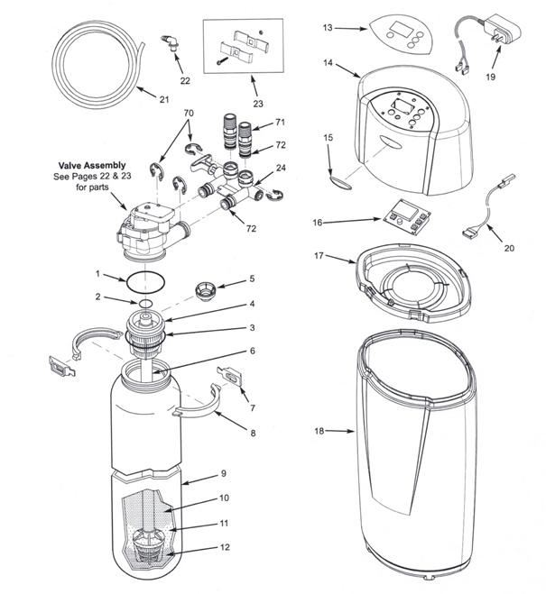
Central Water Filtration System
Parts List
Key No. Part No. Description
- 7290876 Assembly, Replacement Mineral Tank,
w/media & associated components (Includes Key
Nos. I through 12)
– 7112963 Distributor 0-Ring Kit (includes Key Nos. 1-3)
I “ ‘1″ 0-Ring, 2-7/8″ x 3-1/4″
2 “ 0-Ring, 13/16″ x 1-1/16″
3 “ ‘1’ 0-Ring, 2-3/4″ x 3″
4 7077870 Top Distributor
5 7265025 Filter Screen
6 7105047 RepI. Bottom Distributor
– 7331177 Tank Neck Clamp Kit (includes 2 ea. of Key Nos. 7 & 8)
7 “ Retainer Clip (2 req.)
8 “ Clamp Section (2 req.)
9 * Mineral Tank, 8″ x 25″
10 * Activated Carbon, 10 lbs.
11 * Filter Sand, 5 lbs.
12 * Gravel, 6 lbs.
13 7290402 Faceplate Decal
14 7290119 Cover (order decal above and badge below)
15 7336915 Whirlpool Brand Badge
16 7290729 RepI. Electronic Control Board (PWA)
17 7290101 Rim
18 7296296 Outer Shroud Tank
19 7337482 Power Supply, 28V DC
20 7259927 Wire Harness
21 7139999 Drain Hose, 20 ft.
22 1103200 Adaptor Elbow
23 7248706 Ground Clamp Kit
24 7278434 Bypass Valve Assembly, 3/4″, including
2 0-Rings (Key No. 72)
7339997 Owner’s Manual
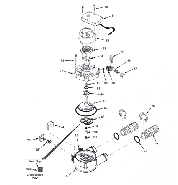
Valve Parts List
Key No. Part No. Description
50 7338111 Screw, #6-19 x 1-3/8″ (2 req.)
51 7281291 Motor
52 7337474 Motor Mount
53 7284964 Cam & Gear
54 7030713 Switch
– 7331274 Drain Hose Adaptor
Kit (incl. Key Nos. 55-59)
55 “ Clip, Drain
56 “ Hose Clamp
57 “ Adaptor, Drain Hose
58 “ 0-Ring, 5/8″ x 13/16″
59 “ Flow Plug, 3.4 gpm
– 7129716 Seal Kit (includes Key Nos. 60-65)
60 “ 0-Ring, 7/16″ x 5/8″
61 “ 0-Ring, 3/4″ x 15/16″
62 “ 0-Ring, 3-3/8″ x 3-5/8″
63 “ Rotor Seal
64 “ 0-Ring, 3/8″ x 9/16″
65 “ Seal, Nozzle & Venturi
66 7082087 Wave Washer
67 7199232 Rotor& Disc
– 7342665 Drain Plug Kit, 3/4″ (includes Key Nos.
64, 68 & 69)
68 “ Plug, Drain Seal
69 “ Spring
70 7337563 Clip, 3/4″, pack of 4
71 7342673 Installation Adaptor, 3/4″, pack of 2,
including 2 ea. Clips & 0-Rings (See
Key Nos. 70 & 72)
72 7337571 0-Ring, 15/16″ x 1-3/16″, pack of 4
73 7082053 Valve Body
74 7081201 Retainer, Nozzle & Venturi
75 7342649 0-Ring, 1/4″ x 3/8″, pack of 2
76 7100940 Plug, Aspirator Port
77 7337466 Valve Cover
78 7342657 Screw, #10-14 x 2″, pack of 5
. * source: Whirlpool document 7339997 (Rev. D 7/22/14)
09.28.15
I recently met a woman who had this water equipment installed. She was not happy with the representative. I told her we can provide all the parts and service she needs to this unit. I hope that we can help other people who may need parts and service throughout Phoenix, AZ for whole house water filtration Buckeye, AZ; Cave Creek, AZ, Scottsdale, AZ, Paradise Valley, AZ for water filtration repair and service. Peoria, AZ we provide service and installation on all whole house water treatment equipment for rental and for sale.
Krystal Klear Water
Water Filtration System &
Electronic DeScaler
Instruction & 0wners Manual
WELCOME
INSTALLATION OVERVIEW BEFORE YOU START PROGRAMMING INSTRUCTIONS – FILTRATION SYSTEM INSTALL INSTRUCTIONS – ELECTRONIC DESCALER NEW SP4000 FITTINGS
FREQUENTLY ASKED QUESTIONS, HELPFUL HINTS
These are the components of this whole House Water Treatment equipment


C-SERIES
Time Clock Series Models
1″ & 1-1/4″ Control Valve
Time Clock Programming Guide

Front Cover and Drive Assemb/y
Part No. Description Qty
C3175TC-01 IC Front Cover Asy 1
C3107-01 Motor Asy 1
C3106-01 Drive Bracket & Spring Clip 1
C3818TC IC PC Board 4-Digit 1
C3110 Drive Reducing Gear l2x363
C3109 Drive Gear Cover 1
C3002TC TCDriveAssemjy.
Not Shown
C3186 AC Adapter l2OV-12V 1
C3186EU AC Adapter 220 240V 12VEU
C3186UK AC Adapter 220-240V-
V3186-01 WS1 AC Adapter Cord Only

Part Shown in picture C3175TC-01

Part shown in picture C3818TC

Part shown in picture C3107-01
Complete assembly part C3002

Parts shown in picture C3110, C3109, C3106-01
Drive Cap Assembly, Down flow Piston, Rçgenerant Piston & Spacer Stack Assembly
Part No. Description Qty
C3430 Spacer Stack Assembly 1
C3004 Drive Cap ASY 1
C3178 Drive Back Plate 1
C3407 Piston Downfl ow ASY 1
C3174 Regenerant Piston 1
C3135 0-ring 228 1
C3180 0-ring 337 1
C3358 0-ring 219 (Dist. Tube Opening 1.32) 1
C3357: 0-ring218(Dist. Tübé Openinq
Not Shown
C3020 Body ASY Downflow (Distributor Tube Opening 1.32”)
C3020-01 1.25 Mixing Valve Body Downflow Assy (Distributor Tube Opening 1.32′)
C3020-02 1.25Body Assy Downflow (Distributor Tube Opening 32mm)
C3020-03 1.25 Mixing Valve Body Downflow Assy (Distributor Tube Opening 32mm)
Part No. Description Qty
C3005 1 ‘Spacer Stack Assembly 1
C3004 Drive Cap Assembly 1
C3178 Drive Back Plate 1
C3011 Piston Downflow Assembly 1
C3174 Regenerant Piston 1
C3135 0-ring 228 1
C3180 0-ring 337 1
C3105 I 0-ring 215 (Distributer Tube) 1
Not Shown
C3001 Body ASYDownflow 1
C3001-02 I Mixing Valve Body ASY
1″ Control Valve Part Numbers C3118
1-1/4′ Control Valve Part Numbers
Applies to Both Size Control Valves
Words in the pictures: Black Plug ,Grey Plug, Grey Ring, Distributor, retainer, Grey Spacer Color , Black Plug
*Only for valves that have a 32mm Distributor Tube Opening
C-Series 1′ & 1-1/4″ Time Clock Manual
C-Series 1″ & 1-114″ Control Valve Identification
C-Series with 1.050″ Distributor Tube Opening Identification

C-Series 1-1/4″ with 1.32H Distributor Tube Opening Identification
Words in picture: Black Spacer Color, Grey Plug
C-Series 14/4″ with 32mm Distributor Tube Opening Identification
Words in picture: Grey Plug, Grey Spacer Color, Grey Ring, Grey Distributor 0-Ring Retainer
C-Series 1 & 1-1/4″ Time Clock Manual

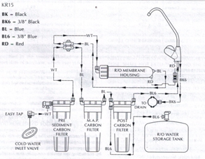
A water softener whole house filtration system sold at Lowe’s Home Improvement stores
Krystal PureTM: KS10, DS15HE, DS64HE, For Water Softener/ Whole House Conditioner Systems
For Scottsdale, AZ, Cave Creek, AZ,

Krystal Pure brine tank assembly ensamblado del Depósito de salmuera
- Take off cap from brine well.
- Take out float assembly.
- Place brine well into brine tank and align brine well holes with brine tank holes.
- Take out 1/2 900 elbow hose barb and remove rubber washer and plastic nut.
- Insert 1/2″ 900 elbow over flow” fitting through bottom hole. Elbow should point towards floor (outside of brine tank)
- Place rubber gasket over threads.
- Push Brine well over threads and tighten plastic nut on threads inside brine well.
- Remove nut from float assembly and position screw into hole on brine well. Then replace nut.

Words in picture:
Brine Tank
Brine Well
½” 90 degree Elbow
Float Assembly
INSTALLATION INSPECTION
IS YOUR HOME PRE-PLUMBED?

Your home is pre-plumbed for a water
softener/conditioner if you have a loop in the
garage or laundry room. Typically, there will be a
110 volt outlet within 6 feet of the loop and a 1/2″;
drain line stubbed out of the wall.
KS15HE AND KS64HE VALVE AND PARTS

PARTS LIST
CODE PART NO. DESCRIPTION QTY
I 1035007 Valve Assembly w/o Flow Controls 1
2 1035615 960 Standard Cam Shaft 1
3 Drain Control Assembly 1
1000209 NO.7 (1.2gpm;4.5Lpm)
1000210 NO .8 (1.6 gpm; 6.1Lpm)
1000211 NO.9 (2.0 gpm; 7.6Lpm )
1000212 No. 10 (2.5 9pm; 9.5Lpm)
1000213 No.12 (3.5 gpm; 13.2Lpm)
1000214 No.13 (4.1 gpm; 15.5 Lpm)
1000215 No. 14 (4.8 gpm; 18.2 Lpm)
4 1035502 Ball Flow Control 1
5 Injector assembly 1
1032970 “A” injector – White
1032971 “B” injector – Blue
1032972 “C” injector – Red
1030272 “D” injector – Green
6 1000269 injector cap assembly 1
7 Brine refill control 1
1000222 .33 gpm
8 1002449 Drain fitting elbow(3/4” hose barbed) 1
9 1000226 Screen cap assembly 1
10 1010429 o – ring 1
11 1035622 tank ring 1
12 plumbing adapter kits 1
1001606 ¾ inch copper tube adapter kit
1001670 1 inch copper tube adapter kit
1041210 1 ¼ inch copper tube adapter kit
1001608 22-mm copper tube adapter kit
1001613 3/4 inch CPVC Tube adapter kit
1001614 1 inch CPVC Tube Adapter Kit
1001615 25-mm CPVC Tube Adapter kit
1001769 ¾-inch NPT Plastic Pipe Adapter kit
1001603 1 inch NPT Plastic Pipe Adapter kit
1001604 ¾-inch BSPT Plastic Pipe Adapter kit
1001605 1-inch BSPT Plastic Pipe Adapter kit
1001611 ¾-inch BSPT Brass Pipe Adapter kit
1001610 1 inch NPT Brass Pipe Adapter kit
1001612 1 inch BSPT Brass Pipe Adapter kit
13 1033444 TURBINE ASSEMBLY 1
14 1001580 SPRING, FLAPPER VALVE
15 1030372 COVER 1
VALVE DISC KIT
1041174 STANDARD
1041175 SEVERE SERVICE
KSI5HE Controller

K8I5HE Source Select, Bypass Valve

K8I5HE Transformer

Code No. Description Qty.
1 KSI5FIE Controller 1
2 1040930 Source Select, bypass value 1
3 1000811 Transformer 1
+ 1000907 Transformer Extension Cord 1
15 feet (4.6 m)
+ 1034264 V-Splitter (run 2 units from 1
1 transformer)
Source Select, Bypass Valve
+ 1040930 Bypass Body Assembly with install Kit 1
+ Not Shown
KS5, KS10 VALVE AND PARTS

Code No. Description Qty.
1 1000232 Valve Assembly, W/0 Flow Controls 1
2 1031950 Camshaft, Standard. One- Piece 1
3 1000062 Valve Cover, Black with transparent window 1
4 Brine refill Flow Control Assembly 1
1034261 1 to 10 lbs Salt
1034263 3 to 19 lbs Salt
5 1000226 Screen/Cap Assembly with O ring 1
6 Backwash Control Assembly with O-rings 1
1034162 No 6 for 6 in Diameter Tank
1000209 No 7 for 7 in Diameter Tank
1000210 No 8 for 8 in Diameter Tank
100211 No 9 for 9 in Diameter Tank
1000212 No 10 for 10 in Diameter Tank
100213 No 12 for 12 in Diameter Tank
100214 No 13 for 13 in Diameter Tank
100215 No 14 for 14 in Diameter Tank
7 1030502 Ball, Flow Control 1
8 Injector Assembly with O-rings 1
1032970 “A” Injector – White
2032971 “B” Injector – Blue
1032972 “C” Injector – Red
9 Injector Cap with O-0ring 1
1000217 “A” Cap
100218 “B Cap”
100219 “C Cap”
10 1033784 Tank Adapter Assembly 1
11 1032416 Air Check Assembly 1
12 1010429 O-Ring BN 1
13 1010428 O-Ring EP 1
14 1031402 Locking Bar: English Language 1
15 1006093 Screw, No 9 x 9/16 inch 1
16 1001580 Spring, Valve Disc Kits: 9
17 1033066 New to Old Aircheck Adapter Kit 1
18 100297 Extended Bearing, Camshaft 1
19 1031391 Pin, Locking, Timer, Black 1
20 Covers, high style
1041087 Beige/ Tan
1041088 Black/ White
1041091 Beige/Black
21 1030501 Bearing, Camshaft for use with Cover (Code 22)
22 1032565 Cover, L-lid
23 1001404 O-Ring Group: Tank Adapter
24 1040459 O-Ring Group: Piping Boss
25 1041010 13/16 inch Riser Insert (optional)
+ 1000250 Valve Disc Replacement
+ Not shown
Source Select Bypass Valve

Code Part No. Description Qty.
1 1040769 Source Select, Bypass Valve 1
2 1040524 Install Kit 1
+ Tube Adapter Kits
1001606 3/4 –inch Copper Tube Adapter Kit
1001670 1-inch Copper Tube Adapter Kit
1001608 22-mm Copper Tube Adapter Kit
1001609 28-mm Copper Tube Adapter Kit
1001613 ¾-inch CPVC Tube Adapter Kit
1001614 1-inch CPVC Tube Adapter Kit
1001615 22-mm CPVC Tube Adapter Kit
1001769 3/4 –inch NPT Plastic Pipe Adapter Kit
1001603 1-inch NPT Plastic Pipe Adapter Kit
1001604 ¾-inch BSPT Plastic Pipe Adapter Kit
1001605 1-inch BSPT Plastic Pipe Adapter Kit
1001611 ¾-inch BSPT Brass Pipe Adapter Kit
1001610 1-inch NPT Brass Pipe Adapter Kit
1001612 1-inch BSPT Brass Pipe Adapter Kit
+ Not Shown
KS5, KS10 Adapter

Code Part No. Description Qty.
1 1032350 Kit, KS5, KS10 Adapter 1
2 1032351 KS5, KS10 Adapter Install Kit 1

KS5, KS10 Controller

Code Part No. Description Qty.
1 KS5, KS10 Controller 1
2 Transformer 1
1000810 Japanese
1000811 North American
1000812 Australian
1000813 British
1000814 European
1000907 Transformer Extension Cord 1
15 foot (4.6m)
KS5, DS10 Piping adapter
Code Part No. Description Qty.
1 Kit KS5, KS10 Piping adapter 1
(includes hardware):
1040277 ¾-inch NPT, Brass
1040278 1-inch NPT, Brass
1040281 3/4-inch BSPT, Brass
1040282 1-inch BSPT, Brass
1040279 3/4-inch NPT, Noryl
1040280 1-inch NPT, Noryl
1040283 ¾-inch BSPT, Noryl
104284 1-inch BSPT, Noryl
2 1040339 KS5, KS10 Piping adapter 1
Install Kit
Brine Tank Assembly
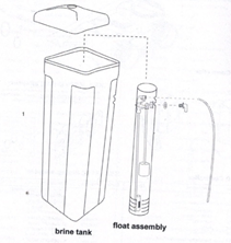
Code Part No. Description Qty.
1 208-11112 KS5 brine tank & assembly kit (black) 1
1 208-11111 KS10, KS15HE brine tank & assembly kit 1
(white)
1 208-14142 KS64HE brine tank & assembly kit 1
Valve Troubleshooting
– Problem Possible Cause Solution
1.Control will not draw brine. a.Low water pressure. A. Set pump to maintain 30 psi
conditioner.
b.Restricted drain line. b.Remove restriction.
C.Injector plugged! c.Clean injector and screen.
d.Injector defective! d.Replace injector.
e.Valve (2 and/or4) not closed. e.Remove foreign matter
from disc and check disc for
closing by pushing in on stem.
Replace if needed.
2.Brine tank overflow, a Brine valve (I) being held open a.Manually operate valve
stem to flush away
obstruction B Uncontrolled brine refill flow rate! b. Remove variable salt
controller to clean. C Valve (3 or 4) not closed during brine c. Flush out foreign matter by
draw causing refill. holding disc open and manually
operating valve stem B Air leak in brine line. d. Check all connections in brine
line for leaks.
Refer to instructions.
3 System using more or less salt A Inaccurate setting, a. Correct setting.
than salt control is set for b.Foreign matter in controller b. Remove variable salt
causing incorrect flow rates controller
and flush out foreign
matter.
Manually position control to brine draw to clean controller
(after so doing, position control
to “purge” to remove brine from tank).
c.Defective control. C. Replace controller.
4 Intermittent or irregular brine draw a.Low water pressure. a.Set pump to maintain 30
psi at softener/conditioner.
b.Defective injector! b.Replace both injector and
injector cap.
5.No soft/conditioned water after a. Unit did not regenerate. aCheck for power.
regeneration. b. No salt in brine tank. b.Add salt.
- Plugged injector! c.Clean injector. Flush with
water.
6.Control backwashes at excessively a.Incorrect backwash a.Replace with correct size
low or high rate. controller used, controller.
b.Foreign matter affecting b.Remove controller and
controller operation! ball. Flush with water.
7.Flowing or dripping water at drain a.Drain valve (5 or 6) or brine a.Manually operate valve
or brine line after regeneration. valve (1) held open by stem to flush away
foreign matter or particle. obstruction.
- Valve stem return spring on b.Replace spring.
top plate weak.
8.Hard water leakage during service. a. Improper regeneration a Repeal regeneration
Making certain that the
correct salt dosage is set.
- Leaking of bypass valve! b.Replace 0-ring. c. 0-ring around riser tube c.Replace 0-ring.
damaged!
KS5 and KS10 -4601 Control Troubleshooting
Problem Possible Cause Solution
Clock does not display time of day. a.Transformer cord unplugged a.Connect power
b.No electric power at outlet. b. Repair outlet or use
working outlet.
- Defective transformer. c.Replace
transformer.
d.Defective circuit board. d.Replace timer.
Clock does not display correct time a transformer cord unplugged a connect power
of day. B No electric power at outlet b repair outlet or use
working outlet
c defective transformer c. replace transformer
- Defective circuit board. D. Replace timer.
a.Outlet operated by switch a Use outlet not controlled by
switch.
- Incorrect voltage or frequency (Hz). b. Replace timer with one of correct
voltage and frequency (Hz).
- Power outages. c.Reset clock.
3.Time display continues to advance. a.Defective time set switch. a. Replace timer.
4.Time display shows something other a.Electrical interference, a Disconnect power to unit.
than time of day. Restore power and reset time
of day.
- defective circuit board. d.Replace timer.
5.No water flow display when water is a.Bypass valve in bypass. a. Shift bypass valve to not-in-
flowing, bypass position.
- Meter probe disconnected or b. fully insert probe into meter
not fully connected to meter housing.
housing.
- Restricted meter turbine c.Remove meter housing, free up
rotation due to foreign matter turbine and flush with clean
in meter. water. Do not disassemble
turbine from meter housing.
Turbine should spin freely. If
not, replace meter!
d.Defective meter probe. D Replace timer.
E Defective circuit board. E Replace timer.
6.Control regenerates at wrong time of a.Power outages. a.Reset clock to correct time of
Day. day.
b.Clock set incorrectly. b.Reset clock to correct time of day.
7.Timer stalled in regeneration cycle. a.Motor dead, a.Replace timer,
b.Motor runs backward. b. Replace timer,
- No electric power at outlet. c.Repair outlet or use working
outlet,
d.Broken gear. d.Replace timer,
e.Defective switch. e.Replace timer.
f.Air leak in brine connections, f.Check all junction points and
make appropriate corrections.
g.Binding of camshaft. g.Remove foreign object
obstruction from valve discs or
camshaft.
- Water pressure greater than 125 h.Install pressure regulator.
psi during regeneration.
- Defective circuit board, i. Replace timer,
- Continuous regeneration, a. Broken switch activator on a. Replace timer.
Camshaft does not stop at the end of gear.
regeneration.
- Defective switch. b. Replace timer.
- Control will not regenerate a. Electric cord unplugged. a.Connect power.
automatically or when button is b. No electric power at outlet. b. Repair outlet or
pressed. use working outlet,
- Defective motor. c. Replace timer.
- Broken gear. d. Replace timer.
- Binding in gear train. e. Replace timer.
f Defective switch. f. Replace timer.
10.Control will not regenerate a. If water flow display is net a.Same as item 5
Automatically, but will regenerate operative, refer to item 5.
when button is pressed. b. Defective circuit board. b. Replace timer.
- incorrect hardness and capacity c. Set to correct
settings. values. See
Programming section.
- Run out of soft water between a. Improper regeneration, a. Repeat
regeneration, making
regenerations. certain that correct salt
dosage is
used.
- Fouled softener resin. b. Use resin cleaner. See Note
1.
- Incorrect salt netting. c. Set salt control to proper
level.
See Salt Setting chart.
- Incorrect harness or capacity d.Set to correct values. See
settings. Programming section.
- Water hardness has increased. e. Set hardness
to new value. See
Programming section.
f.Restricted meter turbine f.Remove meter housing,
free up
rotation due to foreign material turbine and flush with
clean
in meter housing. water. DO NOT
DISASSEMBLE TURBINE
FROM METER HOUSING.
Turbine should spin freely, if not,
replace meter!
g.Excessive water usage below g.Repair leaky plumbing and/ or
1/5 gallon per minute. fixtures!
Note: Use of resin cleaners in an unvented enclosure is not recommended.
KS15HE and KS64HE Performa HE Control Troubleshooting
The KSI5HE/KS64HR continuously monitors itself and sounds an alarm if it detects something wrong. The alarm is beep that is on for one second and then off for nine seconds. When the alarm sounds, the display shows the letters “Err” with a number from Ito 4. The table below lists the Err numbers, a description of each error, the cause of the error, and the solutions. To silence the alarm, press any button on the control. If the error still exists, the control will go back to the alarm condition after 30 seconds.
Indication Description Cause Solution
Err1 I.Electronics Failure a.Control settings need a.Press any key to
reprogramming load default values Refer to
“Programming the valve”
Err2 2.Improper start of a.Valve camshaft has been a.Press any key to silence the
alarm.
regeneration (limit manually rotated daring a (Note: Alarm
automatically clears at
switch closed when it regeneration. “TIME OF REGENERATION”.)
should be open). b. Valve camshaft has been b. The control will tars the motor on and
manually rotated Out of drive the camshaft to the
proper
“regeneration complete” location.
position. c. Replace the control.
- Faulty motor. d.Replace the control.
- Faulty motor drive. e. Replace the control.
e.Faulty switch.
Err3 3. Improper finish of a. Valve camshaft has been a. The control
will turn the motor on and
regeneration (limit manually rotated out of drive the camshaft to the
proper
switch open when it “regeneration complete” location.
should be closed), position.
b.Faulty motor. b. Replace the control.
- Faulty motor drive. c.Replace the control.
d.Faulty switch. d.Replace the control.
Err4 4.Improper control a.One or more settings out a.Hardness: Adjust range: 3 to 250.
settings (one or more of the allowable range. Capacity: Adjust range: 0.1
to 140.0.
settings are of the Refill control: Adjust range: 1 to 99.
allowable range). Brine draw value: Adjust range
Form KPWS030905
Model Fleck 6700 water softener; upflow brining (Rayne RFD Series) Service manual
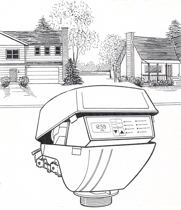
MODEL 6700 Upflow
Meter Assembly
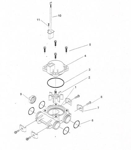
Parts for the 6700 Fleck water softener upflow vavle; Rayne RFD Uplflow valve (Rayne RFD) Upflow: Meter assembly 6700 flex valve
ITEM NO. NO. REQ’D PART NO. DESCRIPTION
1 1 13821 Meter body
2 1 13509 Impeller
3 1 13847 0 ring, -137
4 1 14716 Meter cap assembly, electronic
5 4 12473 Screw, hex washer, 10-24 x 5/8
6 4 13305 O ring, -119
7 4 13255 Clip, mounting
8 4 13314 Screw, hex washer head, 8-18 x 5/8
9 1 14613 Flow straightener
10 1 19121-01 Harness assembly, flow meter
11 1 17798 Screw
MODEL 6700 Upflow
By-Pass Valve Assembly, Brass

Parts for 6700 Fleck (Rayne RFD) Upflow
ITEM NO. NO. REQ’D PART NO. DESCRIPTION• Price
1 1 17290 By-pass valve body, 3/4″
I 17290NP By-pass valve body, 314″ nickel plate
1 13399 By-pass valve body, 1″
1 13399NP By-pass valve body, 1:, nickel plate
2 1 11726 Seal, by-pass
3 1 11972 Plug, by-pass
4 1 11978 Side cover
5 1 13604-01 Label
6 8 15727 Screw
7 1 11986 Side cover
8 1 11979 Lever,by-pass
9 1 11989 Screw, hex head, 1/4 – 14
Model 6700. Rayne RFD water softener
Parts for the 6700 Fleck (RFD): Complete assemblies (Upflw/ Dwnfl)
PART NO. DESCRIPTION
1931 3-XXX Circuit board housing assembly
16944 24 volt motor .
60102-61 Upflow piston assembly
60102-71 Down flow piston assembly
60125 upflow seal kit
60125 downflow seal kit
60022-50 BLFC .50 gpm
60084 Injector/ drain module
60032 Brine valve
17703-10 Upflow valve body assembly
14449 Downflow valve body assembly
14716 Meter cap assembly (dome)
60086-50 Complete meter assembly
60343 Metered power head assembly
Model 6700. Rayne RFD upflow water softener power head
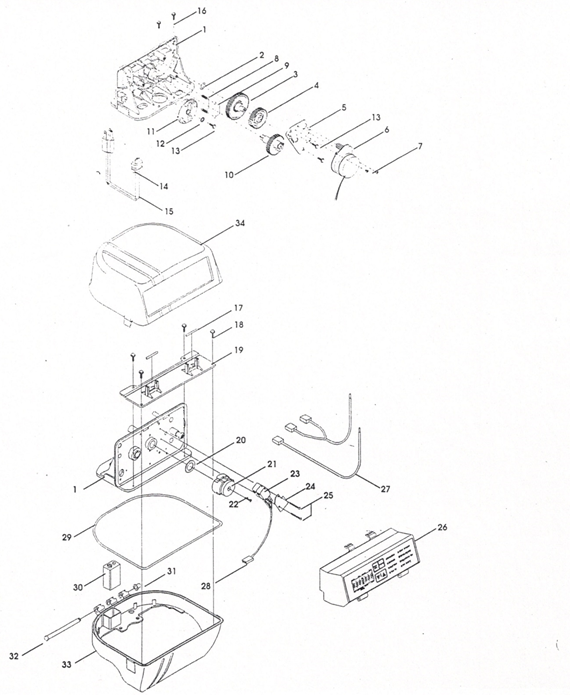
Parts for the 6700 Fleck (Rayne RFD) Upflow: Power head
ITEM NO. NO. REQ’D PART NO. DESCRIPTION
1 1 14193-03 Drive panel
2 1 13299 Spring washer
3 1 13017 Idler gear
4 1 23045 Drive gear
5 1 13175 Motor mounting plate
6 1 16943 Drive motor 2 RPM 120V 60Hz
16944 Drive motor 2RPM 24V 50/60 Hz
16541 Drive motor 2 RPM 220V 50 Hz
7 3 11384 Screw, motor mount
8 2 19080 Spring, detent
9 2 13300 Ball, detent
10 1 24958 Main drive gear and shaft (upflow
Brining-white)
11 1 18722 B/V cam
12 1 12037 Washer
13 7 13296 Screw, component
14 1 13547 Strain relief
15 1 11842 Power cord
16 2 12473 Screw, drive mount
17 2 18754 Pin
18 4 17798 Screw, mounting plate
19 1 17844 Mounting plate
20 1 19079 Friction washer
21 1 24598 Cycle cam (upflow – yellow) backwash first
1 17885 Cycle cam (upflow – red) brine draw/slow
rinse
22 1 15151 Screw, cycle cam
23 2 10218 Microswitch
24 1 10302 Insulator
25 2 17876 Screw, microswitch
26 1 19313-XXX Circuit board housing assy. (state
voltage, if optional relay is installed,
and cycle cam
color)
27 1 19118 Wire harness, power
28 1 1911901 Wire harness, home and step switch
29 1 18&15-01 seal
30 1 9V alkaline batery
31 1 18679 tapered cap
32 1 17845 Hinge pin
33 1 17841-xx Bottom cover (specify color)
34 1 17842-xx Top cover (specify color)
35 4 12681 Wire nut, gray (not shown)
Model 6700. Rayne RFD Upflow water softener – Control valve assembly
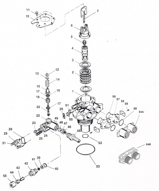
Parts for the 6700 Fleck (Rayne RFD) Upflow water softener – Control valve assembly
ITEM NO. NO. REQ’D PART NO. DESCRIPTION
1 1 17703-20 Valve body, up-flow 13/16″ distributor
1 17703-10 Valve body, up-flow 1″ distributor
2 4 14241 Spacer
3 5 13242 Seal
4 1 18848 Piston – (used with yellow or red cycle
cam)
5 1 14309 Piston rod retainer
6 1 15561 End plug assy – white
7 1 13001-03 piston rod assembly, 6600 up flow
8 not assigned
9 not assigned
10 1 13546 End plug retainer
11 3 12473 Screw
12 1 11981-01 Retaining ring
13 1 16098 Washer brine valve
14 1 11973 Spring brine valve
15 1 13165 Brine valve cap
16 1 12550 Quad ring
17 2 13302 0-ring
18 1 13167 Spacer
19 1 14613 Flow straightener
20 1 13172 Brine valve stem
21 1 12626 Brine valve seat
22 1 13163 Injector housing
23 1 10913 Injector nozzle (specify size)
24 1 10914 Injector throat (specify size)
25 1 10227 Injector screen
26 2 13301 0-ring injector
28 1 13303 0-ring injector cover
.
29 1 13166 Injector cover
31 2 13315 Screw
39 1 13245 BLFC button retainer
40 1 12977 0-ring
41 1 BLFC button (specify size)
42 1 13244 BLFC fitting 3/8″
43 3 10332 BLFC insert 3/8″
44 . 3 10330 BLFC ferrule 3/8″
45 1 13308 Drain hose barb
46 1 13173 DLFC button retainer
47 1 15348 0-ring DLFC retainer
48 1 DLFC button (specify size)
49 1 13333 Injector label
50 1 12638 0-ring drain
51 1 13497 Air disperser
52 1 13304 0-ring distributor tube 1″
1 10244 0-ring distributor tube 13/16″
53 1 12281 0-ring, -338
54A 1 13398 Yoke, brass, 1″ NPT
1 13708 Yoke, brass, 3/4″ NPT
54B 1 18706 Yoke, plastic, 1″ NPT
Parts for Model Fleck 6700; Rayne RFD Upflow water softener
Control valve assembly
ITEM NO. NO. REQ’D PART NO. DESCRIPTION
55 3 10329 BLFC fitting nut
56 2 13255 Adapter clip
57 2 13709 Adapter coupling
58 4 13305 0-ring – adapter coupling
59 2 13314 Screw – adapter coupling
Model 6700 upflow. Rayne RFD
10.27.15 2:45 PM
Model 9000 water softener
Rayne Infinity Water Softener
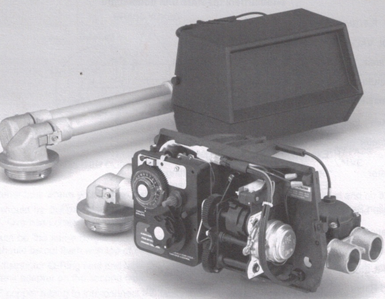
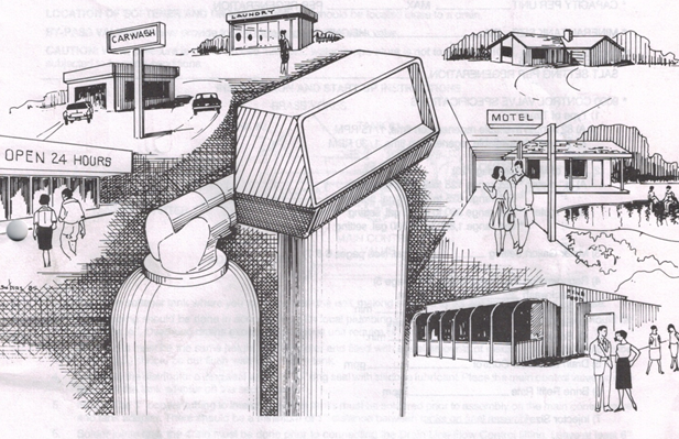
This image portrays the locations the 9000 water softner unit is best suited; a car wash; laundry; motel and restaurants. This model 9000 water softener is designed so there is never a moment of hard water. When one tank is regenerating – the other tank is producing soft water.
This unit is superb for commercial applications where soft water is required 100% of the time.
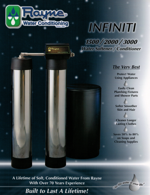
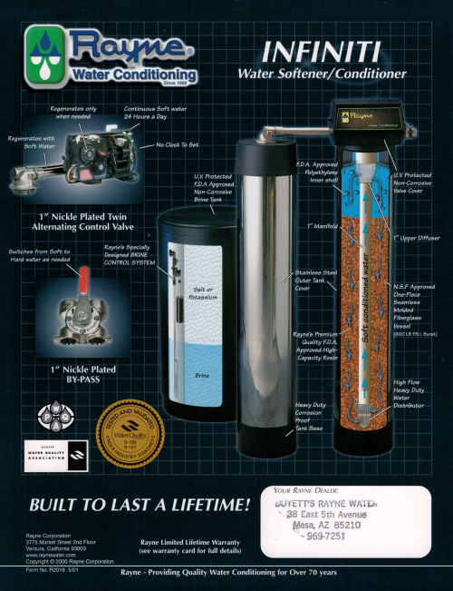
This is the ultimate water softener machine. People love them.
MODEL 9000 ECONOMINDER – Rayne Infinity Home Water Softeners
general, residential & commercial installation
check list
WATER PRESSURE: A minimum of 25 pounds of water pressure is required for regeneration valve to operate effectively.
ELECTRICAL FACILITIES: A continuous 110 volt, 60 Hertz current supply is required. Make certain the current supply is always hot and cannot be turned off with another switch.
EXISTING PLUMBING: Condition of existing plumbing should be free from lime and iron buildup. Piping that is built up heavily with lime and/or iron should be replaced. If piping is clogged with iron, a separate iron filter unit should be installed ahead of the water softener.
LOCATION OF SOFTENER AND DRAIN: The softener should be located close to a drain. BY-PASS VALVES: Always provide for the installation of a by-pass valve.
CAUTION: Water pressure is not to exceed 120 p.s.i., water temperature is not to exceed 110° F, and the unit cannot be subjected to freezing conditions.
INSTALLATION AND START-UP INSTRUCTIONS
- Place the softener tank where you want to install the unit, making sure the tanks are level and on a firm base.
- All plumbing should be done in accordance with local plumbing codes. The pipe size for the drain line should be minimum ½”. Overhead drains exceeding 4′ above unit require 3/4″ drain line.
- Both tanks must be the same height and diameter and filled with equal amounts of media The 1″ distributor tube (1.050 O.D.) should be cut flush with top of each tank.
4.Lubricate the distributor 0-ring seal and tank “o” ring seal with silicone lubricant Place the main control valve on one tank and the tank adapter on the second tank.
- NOTE: The 1″ copper tubing to interconnect the tanks must be soldered prior to assembly on the main control valve and tank adapter. There should be a minimum of 1″ distance between tanks on final assembly.
- Solder joints near the drain must be done prior to connecting the Drain Line Flow Control fitting. Leave at least 6″ between the DLFC and solder joints when soldering. Failure to do this could cause damage to the drain module.
- Teflon tape is the only sealant to be used on the drain fitting.
- Make sure that the floor is clean beneath the salt storage tank and that it is level.
- Place approximately 1″ of water above the grid plate (if used) in your salttank. Salt may be placed in the unit atthis time.
- On units with a by-pass, place in by-pass position. Turn on the main water supply. Open a cold soft water tap nearby and let run a few minutes or until the system is free from foreign material (usually solder) that may have resulted from the installation.
- Place the by-pass in service position and let water flow into the mineral tanks. When water flow stops, open a cold water tap nearby and let run until air pressure is relieved.
12.Electrical: All electrical connections must be connected according to codes. Plug unit into electrical outlet Do not insert meter cable into the meter yet
USA
MODEL 9000 ECONOMINDER water softener drive assembly
Rayne Infinity Home Water Softeners
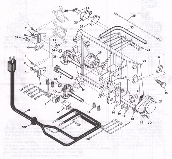
MODEL 9000 ECONOMINDER water softener drive assembly
Rayne Infinity Home Water Softeners
PARTS LIST
ItemNo Quantity Part No Description
1 ………………..2 …………….11335 ………..Screw, #4-40
2 ………………………2 ………………18564 ………..Screw, Hex Washer #6-20
3 ………………………2 …………….13363 ………….Washer
4 …………………….1 ………………….14921 ………..Piston Rod Link, Upper
5 …………………….1 …………………15019 ………..Piston Rod Link, Lower
6 …………………….2 ………………….18728 ………..Nut, Clip, #8-32
7 …………………….1 …………………15203 ………..Wiring Harness – Timer
8 …………………….1 ……………………11838 …………Power Cord
9 ……………………..1 …………………….15202 ………..Wiring Harness – Drive
10 …………………..1 ……………………15134 ………..Driven Gear, Lower
11 ………………1 …………………….15135 ………..Drive Gear
12 …………………..1 …………………….14896 ………..Geneva Wheel
14 ……………………4 . …………………..12681 ………..Wire Connector
15 ………………………2 …………………15236 ………..Cover Screw Assembly
16 ………………………1 …………………..15175 ………..Position Decal
17 …………………….2 …………………….14917 ………..Retaining Ring
18 ………………………1 ……………………..15199 ………..Ground Plate
19 …………………….1 ………………………..14430 ………..Screw, Hex Washer #6
20 …………………….2…………………. ……..19160 ………..Screw, Round Hd #6-32
21 ……. 1 ……………………17509 ………..Drive Motor – 220V., 50 Hz
1 ………………………….14927 ………..Drive Motor – 120V., 60 Hz
1 ……………………………17611 ………..Drive Motor 24V., 50-60 Hz
22 ……………………..1 …………………………..15131 ………..Control Panel
23 ………………………2 ………………………….15172 ………..Screw, Flat Hd #4-40
24 ………………………2 ………………………..10340 ………..Washer, Lock #4
25 ………………………1 ………………………….10218 ………..Micro Switch
26 ……………………….2 ………………………..10339 ………..Nut, Hex #4-40
27 ………………………..7 ………………………..15331 ………..Screw, Hex Washer #10-24
28 ………………………..1 …………………………15133 ………..Drive Gear, Upper
29 ……………………….1 ……………………….15132 ………………..Triple Cam
30 …………………………1 ………………………….13547 ………..Strain Relief
31 ……………………….1 …………………………..15810 ………..Retaining Ring, Drive Gear (not shown)
32 ……………………..1 ……………………………15323 ………..Guide Pin Upper Piston Rod Link
33 ………………………1 ……………………………15368 ………..Cable Guide
34 ……………………….2 ………………………………15372 ………..Washer, Thrust
35 ………………………..1 …………………………………15216 ………..Meter Cable Assy. – 1″ Meter
1 …………………………………………………………15425 ……………Meter Cable Assy. – 3/4″ Meter
36 ……………………….2 ………………………………15692 ………..Spacer
37 ………………………1 ………………………………10302 ………..Insulator (not shown)
38 …………………………….Not Assigned
39 …………………………1 ……………………………….16433 ………..Micro Switch, Program
40 …………………………1 ………………………………….18699 ………..Cover, Top (Now Shown)
41 …………………………1 ……………………………………….14779 ………..Cover, Bottom (Not Shown)
USA
MODEL 9000 ECONOMINDER water softener control valve assembly
Rayne Infinity Home Water Softeners

MODEL 9000 ECONOMINDER water softener control valve assembly
Rayne Infinity Home Water Softeners
PARTS LIST
Item No. Quantity Part No. Description
1……………………1………………… 14861…….. ….. Valve Body
2……………………..1………………..14914 …………Piston, Upper
3……………………..2………………..14309 …………Piston Rod Retainer
2…………. ……16590 …………Piston Rod Retainer, HW
4…………………….1………………..14919 …………Piston Rod, Upper
5……………………2……………………13446 …………End Plug Assy
6…………………….12…………. ……14241 …………Spacer
12………………14241-01 ………Spacer, HW
7…………………….16………………….13242 …………Seal
16………………18759 …………Seal, HW
8………………………1………………14920 …………Piston Rod, Lower
9……………………..1………………..14905 …………Piston, Lower
10……………………1………………11710 …………0-Ring, -215
11…………………..1………………..12281 …………0-Ring, -338
12……………………1……… ……11981-01 ………Retaining Ring
13……………………1……………….16098 …………Washer, Brine Valve (Nylon)
14…………………..1………………….11973 ………….Spring, Brine Valve
15……………………1…………………13165 …………Brine Valve Cap
16……………………3………………….13302 …………0-Ring, -014
17……………………..1…………………….12550 …………Quad Ring, -009
18……………………..1……………….. ……13167 …………Brine Valve Spacer
19……………………..1………………………14925 …………Brine Valve Stem
20……………………..1………………………12626 …………Brine Valve Seat
21………………………1………………………15215 …………Injector Body
22………………………1…………………………10914 …………Injector Throat
10226 …………Injector Throat, SS
23……………………1………………………….10913 …………Injector Nozzle, Specify Size
10225 …………Injector Nozzle, SS
24…………………….1…………………………….13303 …………0-Ring, -021
25…………………….1…………………………….13166 …………Injector Cover
26…………………….1…………………………………16595 …………Spacer
27……………………..1………………………………13387 …………Screw, Hex Hd #10-24
28……………………..1………………………………..13361 …………Spacer, Injector
29……………………..1…………………………………13301 …………0-Ring, -011
30……………………1……………………………….13497 …………Air Disperser
31…………………..1…………………………………15348 …………0-Ring, -563
32…………………..1………………………………….10227 …………Injector Screen
34…………………….1 ………………………………13244 …………B.L.F.C. Fitting
1 ……………………………16173 …………B.L.F.C. Fitting – Bored*
35 1 …………………………………………… B.L.F.C. Button – Specify Size pg. 24
36……………………..1 ………………………………13245 …………B.L.F.C. Button Retainer
37………………………1………………………… …….12977 …………0-Ring, -015
38…………………………….1 …………………….D.L.F.C. Button – Specify Size
39…………………………..1 …………………………………13173 …………D.L.F.C. Button Retainer
40……………………………1………………..10332…Tube Insert – 3/h Note: For Hot Water Delete Items 41 & 42 and
1 15415 Tube Insert – 1/2* use
41……………………………1 ……10330. Ferrule – 3/8” 18698 . . . .Nut & Sleeve Assy. 3/8”
1 …….16124 …………Ferrule – ½”*15414 . .Nut & Sleeve Assy. ½”
42 …………………..1 …….10329 …………Tube Nut-3/8”
1 …….16123 …………Tube Nut – ½”*
43 …………………….1 …….14928 ………….Stub End Plug
44 …………………..1 …….14906 …………End Plate
45 …………………….4 …….15137 …………Screw, Hex Washer, #10-24
46 …………………….1 …….16140 …………Adapter, 1/211 T to 1/411 P (not shown)*
47 …………………….1 …….15471 …………Brine Valve Stand Off
48 …………………….1 …….13315 …………Screw, Hex Washer, #10-24
*These parts are used with #4 Injector and 2 GPM or larger Brine Line Flow Control (B.L.F.C.). Items 34, 35 and 36 are not used.
USA
MODEL 9000 ECONOMINDER water softener – second tank adapter assembly
Rayne Infinity water softener
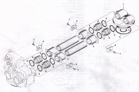
MODEL 9000 ECONOMINDER water softener – second tank adapter assembly
Rayne Infinity water softener
PARTS LIST
Item No Quantity Part No Description
1 ………………………….1 ………14864 ……………2nd Tank Adapter
2 ………………………….8 ………13305 ……………..0-Ring, -119
3 ………………………..1 ………11710 ………………0-Ring, -215
4 …………………………….1 ………12281 ……….0-Ring, -338
5 …………………………..2 ………13708-40 ……..Yoke
1 ………15823 ……….Yoke Assy. Specify Tank Size
6 …………………………4 ………13255 ……….Hold-Down Clip
7 ………………………….4 ………14202 ……….Screw, Hex Hd #8-32
8 ………………………….4 ………15078 ……….Coupling
9 ……………………………2 ……………………………..Pipe – 1″ Copper Cut to Length
U.S.A.
MODEL 9000 ECONOMINDER water softener – air check
Rayne Infinity water softener
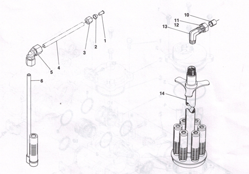
MODEL 9000 ECONOMINDER water softener – air check
Rayne Infinity water softener
PARTS LIST
Item No Quantity Part No Description
1 ………………….1 …………………….10332 ………. Tube Insert /8″
2 ………………….1 ………….10330 ………. Ferrule 3/s
3 …………………..1 ……………………10329 ……….. Tube Nut 3/s”
4 ……………………1 ………Not Supplied ….. Brine Line Tube (s/s Flexible Tube)
5 1 12794 900 Elbow – 3/h1 T to /sI T
1 ………13555 ………. 9Q0 Elbow – 3/Iu T to 3/h1 T, HW
6 ………………………1 ………60002 ………. #500 Air Check Assembly
1 ………60003 ………. #500 Air Check Assembly, HW
For Use With 2 GPM Flow Control
10 ……………………………… 15415……………………. Tube Insert 1/211
11 ……………………………… 16123……………………. Ferrule 1/211
12 ……………………………… 16124……………………. Tube Nut W’
13 ……………………………… 15413……………………. Elbow
14 ……………………………… 60001 ……………………. #700 Air Check Assembly
60006……………………. #700 Air Check Assembly, HW
USA
MODEL 9000 ECONOMINDER – water softener 1″ meter assembly
Rayne Infinity water softener
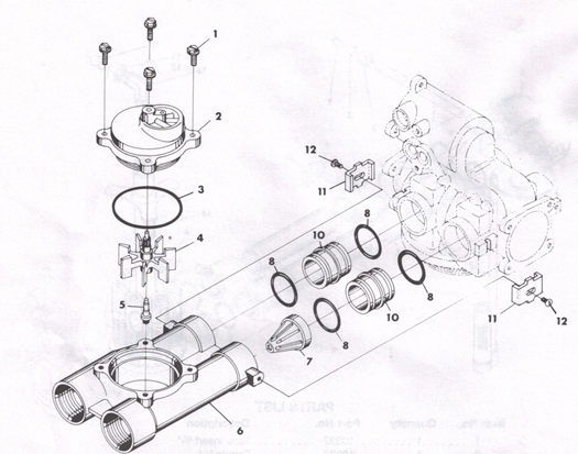
MODEL 9000 ECONOMINDER – water softener 1″ meter assembly
Rayne Infinity water softener
PARTS LIST
Item No Quantity Part No Description
1 ………………………..4 ……………12112 ……….Screw, Hex Hd #10-24
2 ……………………………1 ………15218 ……….Meter Cover Assy.
15237 ……….Meter Cover Assy. (Ext. range)
3 ……………………………..1 ………13847 ……….0-Ring, -137
4 …………………………..1 ………13509 …………Impeller
1 ………13509-01 ……..Impeller, HW
5 ………………………………..1 ………13882 ……….Impeller Post
6 ……………………………….1 ………15043-01 ……..Meter Body 1″ – 111/2 N.P.T.
1 ………15043-02 ……..Meter Body 1″ – 11 B.S.P.
7 …………………………………1 ………14960 ……….Flow Straightener
8 ……………………………………4 ………13305 ……….0-Ring, -119
9 ……………………………Not Assigned
10 …………………………………2 ………15078 ……….Coupling
11 ………………………………2 ………13255 ……….Adapter Clip
12 ………………………………..2 ………14202 ……….Screw, Hex Hd #8-32
U.S.A
MODEL 9000 ECONOMINDER water softener 3/4″ meter assembly
Rayne Infinity water softener
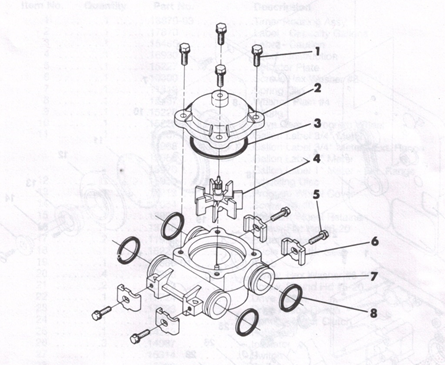
MODEL 9000 ECONOMINDER water softener 3/4″ meter assembly
Rayne Infinity water softener
PARTS LIST
Item No Quantity Part No Description
1 …………………………4 ……….12473 …………Screw, Hex Washer #10-24
2 ………………………….1 ……….14038 …………Meter Cover Assembly – Standard
15150 …………Meter Cover Assembly – Extended Range
3 …………………………..1 ……….13847 ….. . …… 0-Ring, -137
4 ……………………………..1 ……….13509 …………Impeller
5 ………………………………..4 ……….13314 …………Screw, Hex Washer #8-18
6 ……………………………….4 ……….13255 …………Adapter Clip
7 ………………………………1 ……….13821 …………Meter Body
8 ………………………………..4 ……….13305 …………0-Ring, -119
USA
MODEL 9000 ECONOMINDER water softener timer assembly
Rayne Infinity water softener
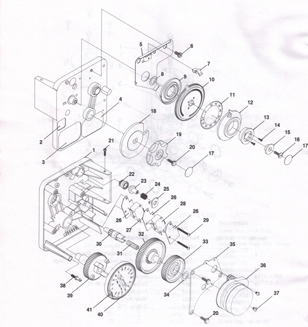
MODEL 9000 ECONOMINDER water softener timer assembly
Rayne Infinity water softener
PARTS LIST
Item No Quantity Part No Description
1 ………………….1 ……13870-03 ……….Timer Housing Assy.
2 ……………………1 ……17870 …………Label – Capacity Gallons
3 …………………….1 ……15465 …………Label – Caution
4 …………………….1 ……16930 …………Label – Instruction
5 ………………………1 ……15227 …………Actuator Plate
6 …………………….1 ……10300 …………Screw, Hex Washer #8
7 …………………….1 ……17513 …………Spring Clip
8 …………………….1 ……15407 ………….Washer, Plain #4
9 …………………….1 ……15228 …………Spring
10 …………………….1 ……15224-01 ……….Drive Gear – Program Wheel
11 ……………………1 ……15967 …………Gallon Label 3/4″ Meter
15968 …………Gallon Label 3/4″ Meter – Ext. Range
15969 …………Gallon Label 1″ Meter
15970 …………Gallon Label 1″ Meter – Ext. Range
12 …………………………1 ……15956 …………Adjusting Disc
13 ………………………..1 ……16218 …………Program Wheel Cover
14 ………………………….2 ……17054 …………Screw, #4-40
15 ………………………1 ……13806 …………Program Wheel Retainer
16 ……………………………1 ……13748 …………Screw, Flat Hd #6-20
17 ………………………….2 ……11999 …………Button Decal
18 ……………………….1 ……15223 …………Cycle Actuator Gear
19 ………………………….1 ……13886-01 ……….Knob
20 ……………………4 ……13296 ………….Screw, Hex Washer #6-20
21 …………………….2 ……15173 …………Screw, Round Hd #5-20
22 ……………………….1 ……17724 …………Drive Pinion
23 ………………………..1 ……17723 …………Drive Pinion Clutch
24 ………………………1 ……14276 …………Spring – Meter Clutch
25 …………………….1 ……14253 …………Retainer
26 ……………………3 ……14087 …………Insulator
27 …………………….1 ……15314 …………Switch
28 ………………………1 ……15320 …………Switch
29 ……………………….2 ……11413 …………Screw, Pan Hd #4-40
30 ………………………1 ……13018 …………Idler Shaft
31 ……………………1 ……18563 ………….Spring – Idler Shaft
32 ………………………….1 ……13017 …………Idler Gear
33 …………………….1 ……13164 …………Drive Gear
34 ………………………1 ……13299 …………Curved Washer
35 ……………………..1 ……13887 …………Motor Mtg. Plate
36 …………………….1 ……13944 …………Motor – 120V 60 Hz.-1/30 RPM
14254 …………Motor – 220V 50 Hz.-1/30 RPM
14973 …………Motor – 120V 60 Hz.-1/15 RPM
15442 …………Motor – 220V 50 Hz.-1/15 RPM
37 ………………………2 ……13278 …………Screw, #6-32
38 ……………………..1 ……14265 …………Spring Clip
39 ………………………1 ……15055 …………Main Drive Gear
40 ……………………1 ……1921 0-05 ……….Program Wheel Assembly – 180 mm.
1 ……1921 0-02 ……….Program Wheel Assembly – 90 mm.
41 …….. ………….20 ……. 15493……………. …………Roll Pin
42 …… Not Assigned
43 …………………….1 ……14430 …………Screw, Hex Washer, #6 (Ground, Not Shown)
U.S.A.
MODEL 9000 ECONOMINDER water softener
Rayne Infinity water softener
service instructions
PROBLEM CAUSE CORRECTION
- Softener Fails To A. Electrical Service To A. Assure Permanent Electrical Service
Regenerate. Unit Has Been Interrupted. Check Fuse, Plug, Pull Chain or Switch).
B Timer Is Defective. B. Replace Timer.
2.Hard Water. A. By-Pass Valve is Open A. Close By-Pass Valve.
B No Salt in Brine Tank B. Add Salt To Brine Tank and Maintain Salt Level
Above Water Level.
- Injector Screen Plugged. C. Clean Injector Screen.
- Insufficient Water Flowing Into Brine Tank D. Check Brine Tank Fill
Time And Clean Brine Line Flow Control If Plugged.
- Hot Water Tank Hardness. E. Repeated Flushings Of The Hot Water Tank is Required.
- Leak At Distributor Tube. F. Make Sure Distributor Tube Is Not Cracked. Check ‘0″ Ring And Tube Pilot
- Internal Valve Leak G. Replace Seals and Spacers And/Or Piston.
3.Unit Used Too Much Salt A. Improper Salt Setting. A. Check Salt Usage and Salt Setting.
4 Loss Of Water Pressure. A. Iron Buildup In Line To Water Conditioner.A. Clean Line To Water
Conditioner.
- Iron Buildup In Water Conditioner. B. Clean Control and Add Mineral Cleaner to Mineral
Bed. Increase Frequency of Regeneration and/or
Backwash Time.
- Inlet of Control Plugged Due to Foreign C. Remove Pistons and Clean Control.
Material Broken Loose From Pipes By Recent
Work Done On Plumbing System.
5.Loss of Mineral Through Drain Line. A. Air In Water System. A. Assure That Well System Has
Proper Air Eliminator Control.
Check For Dry Well Condition.
6.Iron In Conditioned Water A. Fouled Mineral Bed. A. Check Backwash, Brine Draw And Brine
Tank Fill. Increase Frequency Of
Regeneration.
7.Excessive Water In Brine Tank. A. Plugged Drain Line Flow Control. A. Clean Flow Control.
B Plugged Injector System. B. Clean Injector and Screen.
- Timer Not Cycling. C. Replace Timer.
D.Foreign Material In Brine D.Replace Brine Valve Seat
E Foreign Material In Brine Line Flow Control.E Clean Brine Line Flow Control.
8.Softener Fails To Draw Brine. A.Drain Line Flow Control Is Plugged. A.Clean Drain Line Flow Control.
B.Injector Is Plugged. B.Clean Injector.
C.Injector Screen Plugged. C.Clean Screen.
D.Line Pressure Is Too Low. D.Increase Line Pressure To 25P.S.I. Mm.
E.Internal Control Leak. E.Change Seals, Spacers andPiston Assembly.
F.Power Loss During Brine Fill. F.Check Power Source
9.Control Cycles Continuously
A.Broken or Shorted Switch. A.Determine If Switch or Timer
Is Faulty and Replace It or
Replace Complete Power
Head.
- Excessive Water in Brine Tank.
.
10.Drain Flows Continuously. A.Valve Is Not Programed Correctly. A.Check Timer Program and
Positioning of Control.
Replace Power Head
Assembly If not Positioning
Properly.
B.Foreign Material In Control. B.Remove Power Head Assembly And Inspect Bore,
Remove Foreign Material and Check Control In Various
Regeneration Positions.
- Internal Control Leak. C.Replace Seals and Piston Assembly.
General Service Hints
Problem: Softener Delivers Hard Water.
Cause could be that… Reserve Capacity Has Been Exceeded.
Correction: Check salt dosage requirements and reset program wheel to provide additional reserve.
Cause could be that… Program Wheel Is Not Rotating With Meter Output
Correction: Pull cable out of meter cover and rotate manually. Program wheel must move without binding and cycle actuator
must start the cycle before the clutch releases.
Cause could be that… Meter Is Not Measuring Flow.
Correction: Check output by observing rotation of small gear on front of timer (Note – program wheel must not be against
regeneration stop for this check). Each tooth is approximately 75 gallons on 1″ installations. If not performing properly,
replace meter.
Cause could be that. . . Trip Dog On Program Wheel Is Beyond Cycle Actuator Arm.
Correction: 1. If power failed during regeneration; reset program wheel and cycle manually.
2.If exceeding system capacity before regeneration was completed; either a) increase system capacity, b)restrict flow rates, or c) change timer from 164 min./cycle to 82 min./cycle.
3.If defective timer; replace timer.
USA
MODEL 9000 ECONOMINDER water softener
Rayne Infinity water softener
service assemblies
60022-25 …… BLFC .25 GPM 60400……… Piston Assy, 9000 Upper
60022-50 …… BLFC .50 GPM
60022-100 ….. BLFC 1.0 GPM 1 …..11335………Screw, Fil Hd Mach 4-40 X 3/16
1 …… 13446……… End Plug, White Assy
1…… 12094……… Flow Washer .25 GPM 1…… 14309……… Retainer, Piston Rod
12095……… Flow Washer .50 GPM 1…… 14914……… Piston, Upper 9000
12097……… Flow Washer 1.0 GPM 1…… 14919……… Piston Rod, Upper
1 …… 12977 ……… 0-Ring, -015 1 …… 14921 ……… Link, Piston Rod
1 …… 13244……… Adapter, BLFC
1 …… 13245……… Retainer, BLFC Button 60125..Seal & Spacer Kit, 9000 – Upper
60350……… Brine Valve Assy, 9000 5 …… 13242……… Seal
4 …… 14241 ……… Spacer
1 …… 11973……… Spring, Brine Valve
1 …… 11981 ……… Retaining Ring 60421 ……… Seal & Spacer Kit, 9000 – Lower
1 …… 16095……… Washer, Plain #10 Nylon
1 …… 12550……… Quad Ring, -009 11 ….. 13242……… Seal
1 …… 12626……… Seat, Brine Valve 8 …… 14241 ……… Spacer
1 …… 13165……… Cap, Brine Valve i …… 16595 ……… Spacer, 9000
1 …… 13167……… Spacer, Brine Valve
2 …… 13302 ……… 0-Ring, -014 60412……… 9000 Powerhead Assembly
1 …… 14925……… Brine Valve Stem, 9000
60385-XXXX … Injector/Drain Assy 60375-XX ….. 9000, Timer 1/15 RMP
60376-XX 9000, Timer 1/30 RPM
60086……… 3/4″ Meter, Standard Range
60087..3/4″ Meter, Extended Range 60136-9000 . . .9000 Service Repair Kit DLFC, Flow Washers
60389……… 1″ Meter, Standard Range 12085 ……… Flow Washer, 1.2 GPM
– 12086……… Flow Washer, 1.5 GPM
60390……… 1″ Meter, Extended Range 12087……… Flow Washer, 2.0 GPM
12088……… Flow Washer, 2.4 GPM
12089……… Flow Washer, 3.0 GPM
12090……… Flow Washer, 3.5 GPM
60401 ……… Piston Assy, 9000 Lower 12091 ……… Flow Washer, 4.0 GPM
12092……… Flow Washer, 5.0 GPM
12408……… Flow Washer, 7.0 GPM
1 …… 11335……… Screw, Fil Hd Mach 4-40 x 3/16
1 …… 13446……… End Plug Assy White
1 …… 14309……… Retainer, Piston Rod
1 …… 14905……… Piston, Lower 9000
1 …… 14920……… Piston Rod, Lower
1 …… 15019……… Link, Piston Rod
U.SA
MODEL 9000 ECONOMINDER WATER softener
Rayne Infinity water softener
service assemblies, hot water
60612…………….1″ Meter, Standard Range, HW
60401-01 ……….Piston Assy, 9000 Lower, HW
1 ……………..11335 ……………… Screw, Fil Hd Mach 4-40 x 3/16
1 ……………..11335-01 ………….End Plug Assy White
1 ……………..16590 ……………… Retainer, Piston Rod, HW
1 ……………..14905 ……………… Piston, Lower 9000
1 ……………..14920 ……………… Piston Rod, Lower
1 ……………..15019 ……………… Link, Piston Rod
60400-01 ……….Piston Assy, 9000 Upper, HW
1 ……………..11335 ………………Screw, Fil Hd Mach 4-40X3/16
1 ……………..13446-01 ………….End Plug, White Assy
1 ……………..16590 ………………Retainer, Piston Rod
1 ……………..14914 ………………Piston, Upper 9000
1 ……………..14919 ………………Piston Rod, Upper
1 ……………..14921 ………………Link, Piston Rod
60125 HW………Seal & Spacer Kit, 9000 – Upper, HW
5……………..18759 ………………Seal
4……………..14241-01 ………….Spacer
60421 HW………Seal & Spacer Kit, 9000 – Lower, HW
11 ……………18759 ………………Seal
8……………..14241 -01 ………….Spacer
1 ……………..16595 ………………Spacer, 9000
U.S.A.
01.18.16 8:05 AM

Rayne 5066 Water Softener
Owner’s manual 5066
This manual contains information on setting the controller and normal operating maintenance required by the owner for the following units: RG 1250, RXD 1000, RXD 1500, & RXD 1500D
Water Quality Association tested and certified under industry standards
Owner’s Manual
Water Softener Assembly
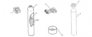
Item # RG-1 250 DESCRIPTION – Rayne Guardian
1 5066103 RXD Controller – Specify Tank Size
1 A 18259-02 RXD Front Cover
2 60049 Bypass, plastic with 1″ yoke
3 RF0030 High Flow Distributor – Specify Tank Size
4 10 x 47 Mineral Tank
5 1/4 CF Filtrex Media
6 1-1/4 cf High Capacity Resin, Solvent Free
7 8 lbs. Support Bed – Gravel
8 10″ Collar – Black
9 Stainless Steel Jacket
10 10″ Tank Base
Item # RXD 1000 RXDI000S* RXD 1500 RXDI500-D Description
1 5066103 RXD Controller -Specify Model
2 60049 Bypass, plastic 1″
3 ST1040 ST1035 ST1047
10 x 40 10 x 35 10 x 47 Mineral Tank
4 RF00011 n/a RF00011 Tank Base
5 RF0030 High Flow 1′ Distributor – Specify Model
6 A1020-5 High Capacity Resin, C-249
1 cf 1cf 1.5 cf 1.5 cf
7 CK1040 n/a CK1040 SS1047
Almond Almond Stainless Steel jacket
10×40 10×47 10×47
8 RF00015 n/a RF000I5 SS0010 Collar – Black
9 n/a CK1111 n/a n/a Cabinet
10 n/a CK0011 n/a n/a Cabinet Deck
* Model RXD 1000S is not WQA Certified.
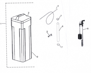
Item # RG-1 250 DESCRIPTION
1 C10772 BR 15″ x 17″ Complete Brine Tank Assembly
2 B08802 BR 15″ x 17″, Black Brine Tank
3 A10171 BR 15″ x 17″, Black Brine Tank Lid
4 A11510 BR Brine Line
5 A13940 BR Overflow Fitting
6 A14120 BR Brine Well
7 A05300 BR (2) Brine Well Lid
8 2310/500 Brine Valve Assembly
Owner’s Manual
Control Valve Assembly
Owner’s Manual
Brine Tank Assembly
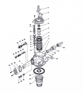
Owner’s Manual
Down Flow Control Valve
Item No Quantity Part No Description
1 …………. ….1 ………..18815……………Valve Body, 5000, 1 “Dist.
2…………. ….1 ……….. 18264…………………..Spacer, End
3……….. ……4 ………..14241 …………………..Spacer
4…………….. 5 ………..13242………………….. Seal
5…………… 1 ………..18265………………….. Piston, Downflow
6…………….. 1 ………..14309………………….. Retainer, Piston Rod
7…………….. 1 ………..18268………………….. End Plug Assembly
8…………….. 3 ………..18261 ………………….. Screw, Hex Washer Head, 1024 x 13/16
9…………….. 1 ………..18267………………….. Piston Rod
10 ……….. 1 ………..17978………………….. Brine Valve Stem
11 ……….. 1 ………..18755………………….. Seat, Brine Valve
12 ………….1 ………..13167………………….. Spacer, Brine Valve
13 …………1 ………..12550………………….. Quad Ring, 009
14 ……….. 2 ………..13302………………….. 0 Ring, 014
15 ……….. 1 ……….. 13165 …………………… Cap, Brine Valve
16 ……….. 1 ………..11973 ………………….. Spring, Brine Valve
17 …………1 ………..16098………………….. Washer, Plain, Nylon
18 ……….. 1 ………..11981 01 ……….. Retaining Ring
19 ……….. 1 ………..11183 ………………….. 0 Ring, 017
20 ………. 1 ………..2.4 GPM ……….. Flow Washer
21 ……….. 1 ………..11385 01 ……….. Flow Control Housing, Plastic
22 ……….. 1 ………..18312………………….. Retainer, Drain
23 ……….. 1 ………..13304………………….. 0 Ring, 121
24 ……….. 1 ………..18303………………….. 0 Ring, 336
25 ……….. 2 ………..10141 ………………….. 0 Ring, 010
26 ……….. 1 ………..18276………………….. Plug, Injector
27 ……….. 2 ………..13771 ………………….. 0 Ring, 012
28 ……….. 1 ………..18275 X………….Injector Throat (specify size) 000, 00, 0, 1, 2, 3
29 …………1 ………..18274 X ………….Injector Nozzle (specify size) 000, 00, 0, 1, 2, 3
30 ……….. 1 ………..18273………………….. Vortex Generator
31 ……….. 1 ………..18271 ………………….. Screen Injector
32 ……….. 1 ………..18301 ………………….. Seal, Injector
33 ……….. 1 ………..18277………………….. Cap, Injector, Softener
34 ……….. 2 ………..18262………………….. Screw, Hex Washer Head, 10 24 x 1
35 ……….. 1 ………..12977………………….. 0 Ring, 015
36 ……….. 1 ………..13245………………….. Retainer, BLFC Button
37 ……….. 1 ………………………………………. Flow Washer (specify size)
38 ……….. 1 ………..13244………………….. Adapter, BLFC
39 ……….. 1 ………..13308………………….. Hose Barb, Black, 1/2 x 112 Straight
1 ………….12338 …………………. Hose Barb, Black, 1/2 x 1/2 900 Elbow
40 ……….. 1 ………….18280 …………………. Top Collector, 1 X.011, Gray
Owner’s Manual
Control Drive Assembly
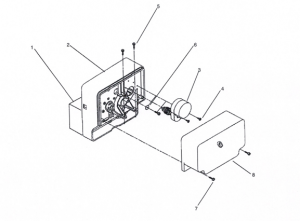
Item No Quantity Part No. Description
1 …….. ………..1 .. ….EB5066………. Electronic Board
2 …………… ….1 . …..60200-00 ……. Control Drive Assembly, Downflow
3 …………….. ..1 .. ….18217-10 ……. Motor Assembly 24V /60 Hz
4 ………….. …..2 …… 13602 ………… Screw, Rd Head, 6-32 x 5/16
5 ……………. …2 ……18261 ………… Screw, Hex Head, 10-24 x 13/16
6 …………… ….1 … …13363 ………… Washer, Plain .145 ID
7 ………….. …..4 …. ..13296 ………… Screw, Hex Washer 6-20 x 1/2
8 ………… …….1 … …18259-02……. Cover, Back, Black
Owner’s Manual
Turbine Meter Assembly
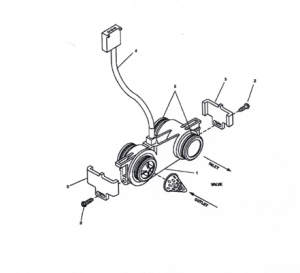
Item No. Quantity Part No Description
1 ….. 1 .. 19797 ………………..Meter Assembly, Turbine
2 …… 1 . 13314 ………………..Screw, Hex Washer, 18-18 x 5/8
3 ………. 1 19569 ………………..Clip, Flow Meter
4 ………. 1 19791-01 ……………Meter Cable Assembly, Turbine
5…………… 4 ..13305 ………………..0 Ring, 119
6 ………. 4 14613 ………………..Flow Straightener
Owner’s Manual
By-Pass Assembly
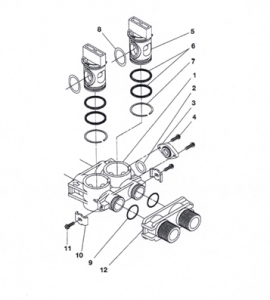
Item No. Quantity Part No Description
1 …………… .1 …. .. 19723 ……………………By Pass Valve Body, Plastic
2 …….. ………..1 … …11183………………………..0 Ring, 015
3 …….. ………..1 … …19724 ……………………….Cap, By Pass
4…………. ……2 . …..17512 ……………..Screw, Hex Washer Head, #624×3
5 ……………. …2 …. ..17820 ……………………….Plug, By Pass
6 ………. ………4 … …18661 ……………………….0 Ring, 218
7 ….. …………..2 . …..18662 ……………………….Retaining Ring
8 ………… …….2 … …18660 ………………………. ORing
9 …….. ………..2 . …..13305 ……………………….0 Ring, 119
10 ……………..2 …. ..13255 ……………………….Clip, Mounting
11 ……………..2 … …13314 ……………………….Screw, Hex Washer Head, 818×5/8
12 …………1 18706………………………Yoke, Plastic, 1 “NPT
1 …. ..8706 02 …………………….Yoke, Plastic 3/4″ (not pictured)
1 …. ..19620-01 …………90° Adapter Coupling – Optional (not pictured)
Owner’s Manual
2310\500 Safety Brine Valve Assembly
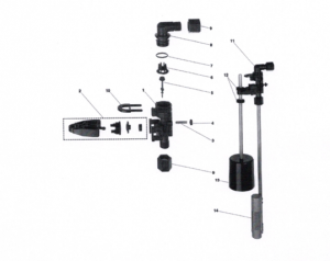
Item No Quantity Part No Description
1 . ………..1 ………….. 19645……………….. Safety Brine Valve Body
2…………….. 1 ………….. 19803……………….. Safety Brine Valve Arm Assembly
3…………….. 1 ………….. 19804……………….. Stud, 1024
4…………….. 1 ………….. 19805……………….. Nut, 1024
5…………….. 1 ………….. 1965201 …………… Poppet & Seal
6…………….. 1 ………….. 19649……………….. Flow Dispenser
7…………….. 1 ………….. 11183 ……………….. 0 Ring, 017
8 …………….. 1 ………….. 19647……………….. Elbow, Safety Brine Valve
9 …………….. 2 ………….. 19625……………….. Nut Assembly, 3/8
10…………… 1 ………….. 18312……………….. Retaining Clip
11…………. 1 ………….. 60014……………….. Safety Brine Valve, 2310 (includes
items 1 10)
12…………… 2 ………….. 10150……………….. Grommet (included with item 13)
13…………… 1 ………….. 60068 ……………….. Float Assembly, 2310
14…………… 1 ………….. 60002……………….. 500 Air Check Assembly
Owner’s Manual
Service Instructions
- -To Remove and Replace Powerhead
- Turn oft water supply to conditioner: a. If the conditioner installation has a “three valve” by pass system, first open the valve in the bypass line, then close the valves at the conditioner inlet and outlet.
- If the conditioner has an integral by pass valve, put it in the by pass position. c. If there is only a shut off valve near the conditioner inlet, close it. 2. Relieve water pressure in the conditioner by putting the control in the backwash position momentarily. Return the control to the service position. 3. Unplug electrical cord from outlet. 4. Disconnect the cable from the meter cover. Remove the control valve back cover. 5. Remove screw and washer at drive yoke. Remove powerhead mounting screws. The entire powerhead assembly will now slide forward.
- Put new powerhead on top of valve. Place lugs atop end plug and slide rearward. Be sure
drive pin on main gear engages slot in drive yoke (rotate control knob if necessary). 7. Replace powerhead mounting screws. Replace screw and washer at drive yoke.
- Return by pass or inlet valving to normal service position. Water pressure should now
be applied to the conditioner, and any by pass line shut off.9. Plug electrical cord into outlet. 10. Set time of day, program wheel, and salt usage. Cycle the control valve manually to assure proper function. Make sure the control valve is returned to the service position. 11. Replace the control valve back cover. Set top leading edge of cover over the 2 legs and rotate down 12. Make sure there is enough brine in the brine tank.13. Plug cable into meter cover. 14. Press the Extra Cycle button to allow the unit to regenerate that evening.
- To Remove and Replace Motor 1. Follow steps Al through A4. 2. Remove the clear Motor Bearing on the front face of the powerhead by turning clockwise. 3. Disconnect wire nuts on motor leads and powercord. 4. Remove the two screws holding motor in place and pull motor out of powerhead. Note:You may have to rock motor slightly to theside. 5. Place new motor in position. Motor should setflush with powerhead and install the two screws.6. Reconnect motor leads and powercord and installwire nuts. Note: Motor leads should be wrapped clockwise around the motor coil to keep clear of the mechanical operation of the
Control Valve.
- Install the clear Motor Bearing on the front face of the powerhead. B. To Replace or Clean Injectors and Screen 1. Follow steps Al through A3. 2. Remove the two screws in the injector cap. Remove injector cap and discard seal. With screwdriver, pry injector nozzle and throat assembly from valve body. 3. Push in cleaned or new injector nozzle and throat assembly. Be sure they are all the way in. Clean or install a new screen. 4. Install new Injector cap seal in Valve Body. 5. Insert screws through injector cap into mating 6. holes in the valve body and tighten screws. 7. Return by pass or inlet valving to normal service position. Water pressure should now be applied to the conditioner and any by pass line shut off. Check for leaks at seal around injector cap. C. To Replace Piston and/or Seals and Spacers and/or Brine Valve Follow steps A1 through A.5. Remove the three screws and pull upward on end plug and piston assembly to remove it from
Valve Body.
- To Replace Brine Valve a. Pull brine valve from valve body, also remove
and discard o ring at bottom of brine valve hole b. Apply silicone lubricant to new o ring andreinstall at bottom of brine valve hole. c. Apply silicone lubricant to new o ring on new brine valve assembly and press into place, shoulder on bushing should be flush with valve body. 4. To Replace Seals and Spacers: a. Remove seals and spacers using your fingers from valve body. b. Inspect the inside bore of the valve for foreign matter that could interfere with valve operation. c. Replace new seals and spacers using your fingers to set in place. 5. To Replace Piston: a. Inspect the inside of the valve to make sure that all seals and spacers are in place, and that there is no foreign matter that could interfere with valve operation.b. Take new piston and end plug assembly as furnished and push piston into valve by means of the end plug.6. Install and tighten the three screws in the end plug.7. Return by pass or inlet valve to normal service position. Water pressure should now be applied to the conditioner and any by pass line shut off.
- Check for leaks at all seal areas. 9. Follow steps A6 through A14. E. To Replace Meter
- Turn off water supply to conditioner: a. If the conditioner installation has a “three valve” by pass system, first open the valve in the by-pass line, then close the valves at the condi-tioner inlet and outlet. b. If the conditioner has an integral by pass valve, put it in the by pass position. c. If there is only a shut off valve near the conditioner inlet, close it. 2. Relieve water pressure in the conditioner by putting the control in the backwash position momentarily. Return the control to the service position. 3. Unplug electrical cord from outlet.4. Disconnect the cable from meter assembly. 5. Remove two screws and clips at by pass valve or yoke. Pull resin tank away from plumbing connections.6. Remove two screws and clips at control valve. Pull meter module out of control valve. 7. Apply silicone lubricant to four new o rings and assemble to the four ports on new meter module.8. Assemble meter to control valve. Note, meter portion of module must be assembled to valve outlet. 9. Attach two clips and screws at control valve. Be sure clip legs are firmly engaged over lugs. 10. Push resin tank back to the plumbing connections and engage meter ports with by pass valve or yoke. 11. Attach two clips and screws at by pass valve or yoke. Be sure clip legs are firmly engaged over lugs. 12. Return by pass or inlet valving to normal service position. Water pressure should now be applied to the conditioner, and any by pass line shut off. 13. Check for leaks at all seal areas. 14. Plug electrical cord into outlet. 15. Set time of day. Make sure the control valve is in the service position. 16. Plug cable into meter assembly. F. Replace Filtrex media 1. Approximately every 2 years contact your local Rayne Dealer.
Owner’s Manual
Trouble Shooting Guide
SYMPTOM
- Softener fails to
regenerate automatically.
PROBABLE CAUSE CORRECTION
- Cord plugged into intermittent A.Connect to constant power
or dead power source. source.
- Disconnected meter cable. B. Reconnect cable
- Defective power cord. C.Replace cord.
D.Defective controller or meter. D.Replace or repair.
SYMPTOM
- Regeneration at wrong time.
PROBABLE CAUSE CORRECTION
A.Controller improperly set, due A.Reset timer
to Power failure B. Check battery.
SYMPTOM
- Loss of capacity.
PROBABLE CAUSE CORRECTION
A.Increased raw water hardness. A.Connect to constant
automatically.
B.Brine concentration and for quantity. B.Keep full of
salt at all times. Clean
it yearly. Salt may be
bridged.
- Resin Fouling. C.Call dealer, find out how
to confirm it, clean the
resin and prevent future
fouling.
D.Poor distribution, Channeling D.Call dealer. Check
(uneven bed surface). distributors and
backwash flow.
E.Internal valve leak. E.Call dealer. Replace
spacers, seals and/or
piston.
F.Resin age. F.Call dealer. Check for
resin oxidation caused
by Chlorine. Mushy resin.
G.Resin loss. G.Call dealer. Check for correct
bed depth. Broken distributors. Air or gas in
bed: Well gas eliminator Loose brine line.
SYMPTOM
- Poor water quality.
PROBABLE CAUSE CORRECTION
- Check items listed in #3. A. Check items listed in #3.
- Bypass valve open. B. Close bypass valve.
- Channeling. C. Check for too slow or high
flow. Check for media fouling.
SYMPTOM
- High salt usage.
PROBABLE CAUSE CORRECTION
- High Salt setting. A. Adjust salt setting.
- Excessive water in brine tank. B. See symptom No. 7.
SYMPTOM
- Loss of water pressure
PROBABLE CAUSE CORRECTION
A.Scaling/Fouling of inlet pipe A.Clean or replace pipeline.
or dead power source. Pre-treat to prevent.
B.Fouled resin. B. Clean the resin.Pre-treat to
prevent.
- Improper backwash. C.Too many resin fines and/or
sediment. Call dealer, reset
backwash flow rate, and/or
adjust time.
SYMPTOM
- Excessive water in brine tank
and/or salty water to service.
PROBABLE CAUSE CORRECTION
A.Plugged Drain Line A.Check flow to drain, clean
flow control.
B.Dirty or damaged brine valve. B.Clean or replace brine valve.
- Plugged injector C.Clean injector and replace screen.
D.Low inlet pressure. D.Increase pressure to allow
injector to perform properly (20 psig minimum).
E.Timer not cycling. E.Replace timer.
SYMPTOM
- Softener fails to use salt.
PROBABLE CAUSE CORRECTION
A.Plugged/restricted drain line. A.Clean drain line and/or flow
control.
B.Injector is plugged. B. Clean or replace injector and
screen.
- No water in brine tank. C.Check for restriction in BLFC.
Ensure safety float is not stuck.
D.Water pressure is to low. D.Line pressure must be at least
20 psi.
E.Brine line injects air during brine draw. E.Check brine line for air leaks.
F.Internal control leak. F.Call dealer, check piston, seals,and spacers
for scratches and dents.
SYMPTOM
- Control cycles continuously.
PROBABLE CAUSE CORRECTION
A.Faulty timer. A.Replace timer.
SYMPTOM
- Continuous flow to drain.
PROBABLE CAUSE CORRECTION
A.Faulty timer. A Call dealer, clean valve,
rebuild unit.
B.Internal control leak. B. Same as above.
- Valve jammed in brine C.Same as above
refill unit.
- Valve motor stopped or jammed. D.Replace valve motor.
60015 1610 Brine Valve
For Illustration, see page 10
1 ……………. 11973 ………….. Spring, Brine Valve
1 …………… 11981 01 ……… Retaining Ring
1 …………… 12550………….. Quad Ring, 009
1 …………… .13165 ………….. Cap, Brine Valve
1 …………… 13167 ………….. Spacer, Brine Valve
2 …………… 13302………….. 0 Ring, 014
1 …………… 16098 ………….. Washer, Plain, Nylon
1 …………… 17978 ………….. Brine Valve Stem
1 …………… 18755………….. 0 Ring, 201
6002212 ……… BLFC.1125 GPM
6002225 ……… BLFC.25 GPM
6002250 ……… BLFC.50 GPM – Standard
60022100 ……. BLFC 1.0 GPM
1 ………….. 17307 …….. …… Flow Washer. 125 GPM
12094………….. Flow Washer.25 GPM
12095………….. Flow Washer.50 GPM
12097………….. Flow Washer 1.0 GPM
1 …………..12977………….. 0 Ring, 015
1 …………..13244 ………….. Adapter, BLFC
1 …………..13245 ………….. Retainer, BLFC
6011500 ……… Piston Assembly, Downtlow
1 …………..14309 …………..Retainer, Piston Rod
1 …………..18265 …………..Piston, Downflow
1 …………..18267 …………..Piston Rod
1 …………..18268 …………..End Plug Assembly
60120…………..Seal and Spacer Kit
5 …………..13242…………..Seal
4 …………..14241 …………..Spacer
1 …………..18264…………..End Spacer
18272000 ……. 1610 Injector Assy., 000, Brow
1827200……… 1610 Injector Assy., 00, Violet
182720 ……….. 1610 Injector Assy., 0, Red
182721 ……….. 1610 Injector Assy., 1, White
182722 ……….. 1610 Injector Assy., 2, Blue
182723……….. 1610 Injector Assy., 3, Yellow
1 ………….10141 …………… 0 Ring, 010
1 ………….13771 …………… 0 Ring, 012
1 ………….18273…………… Vortex Generator
1 …………..18274 XX……… Injector Nozzle
1 ………….18275 XX……… Injector Throat
60280 0001610 Injector Kit, 000, Brown
6028000 1610 Injector Kit, 00, Violet
602800 1610 Injector Kit, 0, Red
602801 1610 Injector Kit, 1, White
Model 1000 & 1500
602802 1610 Injector Kit, 2, Blue –
Model 2000
602803 1610 Injector Kit, 3, Yellow
1 …………….18271 …………..Screen, Injector
1 ……………..18272 XX………..1610 Injector Assembly
1 ……………..18277 …………….Cap, Injector
1 ……………..18301 …………….Seal, Injector
2 ……………..18262 …………….Screw, Hex Washer Head,
10 24 x 12
CD5066 Control Drive Assembly
60086-50 …. 3/4″ Meter
60049……….Bypass, Plastic
6070500 ….. DLFC BLANK
6070506 ….. DLFC .60 GPM
6070508 ….. DLFC .80 GPM
6070510 ….. DLFC 1.0 GPM
6070512 ….. DLFC 1.2 GPM
6070513 ….. DLFC 1.3 GPM
6070515 ….. DLFC 1.5 GPM
60705 17….. DLFC 1.7 GPM
6070520 ….. DLFC 2.0 GPM
6070524 ….. DLFC 2.4 GPM
Model 1250
6070530 ….. DLFC 3.0 GPM
60705 35 …. DLFC3.5 GPM
60705 40 …. DLFC 4.0 GPM
6070545 ….. DLFC 4.5 GPM
6070550 ….. DLFC 5.0 GPM
6070560 ….. DLFC 6.0 GPM
6070570 ….. DLFC 7.0 GPM
1 …………….11183 0 Ring, 017
1 …………………..11385 01 ….. DLFC Housing Plastic
Flow Washer (specify size)
02.01.16 7:44 AM
Rayne Versa Service Manual

Water Conditioning
This manual contains information on setting the controller
and normal operating maintenance required by the owner.
This valve can be used on any tank but comes standard on the Rayne Versa Softeners listed on the following page
Rayne Versa Service Manual
MODEL NUMBERS DESCRIPTION COMMENTS
— Upflow Models
RVU-1000 Upflow Brining, 1 cubic foot of resin U is for Upflow Brining
RVU-1500 1.5cubicfeetof resin
RVU-2000 2 cubic feet of resin
Downflow Models
RVD-1000 RVD-1000-M Downflow Brining, 1 cubic foot of resin D is for Downflow Brining
Msuffix is for adding the mixing valve to allow settings with some
hardness “bleed by”
RVD- 1500 RVD-1500M 1.5 cubic feet of resin
RVD-2000 RVD-2000-M 2 cubic feet of resin
Valve only
Rayne Versa Upflow Valve Valve only
Rayne Versa Downflow Valve Valve only
Rayne Versa DM Valve Valve only
Service Manual
Water Conditioning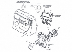
ER Manual
ER Front Cover and Drive Assembly
Drawing No. Order No. Description Quantity
V3381-OIEG WS1ER FRONT COVER ASSEMBLY BLACKIGOLD 1
1 V3381-01ES WS 1ER FRONT COVER ASSEMBLY BLACK/SILVER
2 V3107-01 WS1 MOTOR 1
3 V3106-01 WS1 DRIVE BRACKET & SPRING CLIP 1
4 V3491ER-01BOARD WS1 THRU 2L ER PC BOARD REPLACE 1
5 V3110 WS1 DRIVE REDUCING GEAR 12X36 3
6 V3109 WS DRIVE GEAR COVER 1
V3186 WS AC ADAPTER 11OV-12V 1
V186EU WS AC ADAPTER 220..240V-12V EU
Shown Not V3186UK WS AC ADAPTER 22O-240V-12VUK
V3186-01 WS1 AC ADAPTER CORD ONLY
Not Shown V3382 WS1ER DRIVE BACK PLATE
For software revs E203.6 and lower
Relay Specifications: To insure proper fit and correct operation use either of the 14cc relay/relay socket
combinations or the exact equivalents.
Manufacturer Option 1 Option 2
Relay Socket Idec SR3P-05C SY4S05C
Relay Idec RR2KP-UAC12V / RR2KP-LJCACl2V RY2KS-UACl2V
The relay supplies 2 sets of dry contacts for user applications.
The wiring of these contacts is application specific.
Wiring For Correct On/Off Operation
PC Board Relay Terminal Relay Socket Model
Block
SR3P.05C SY4S-05C
SET #2 #13
COM #6 and #l0 #12 and #14
RES #3 #9
For software revs E204.5 and higher
Relay Specifications: 12V DC Relay with a coil resistance not
less than 80 ohms. If mounting the relay under the cover check-
for proper mounting location dimensions on the backplate.
Wiring For Correct On/Off Operation
PC Board Relay Relay
Terminal Block
RLY1 Coil –
COM Coil +
AC Adapter U.S. International
Supply Voltage 120 VAC 230VAC
Supply Frequency 60 Hz 50 HZ
Output Voltage 12VAC 12VAC
Output Current 500 mA 500 mA
When replacing the battery, align
positives and push down to fully seat.
ER Manual
OEM General Instructions
The control valve offers multiple procedures that allow the valve to be modified to suit the needs of the installation. These procedures are:
- OEM Setup
- OEM Softener System Setup
- OEM Filter System Setup
- Installer Display Settings
- User Display Settings
- Diagnostics
- Valve History
Once the OEM Setup has been set, the other procedures can be accessed in any order. Details on each of the procedures are provided on the following pages.
At the discretion of the manufacturer, the field technician can access all settings. To “lock out” access to diagnostic and valve history displays and modifications to settings except hardness, day override, time of regeneration and time of day by anyone but the manufacturer, press V. NEXT, ^, and SET CLOCK in sequence after settings are made. To “unlock”, so other displays can be viewed and changes can be made, press V, NEXT, ^, and SET CLOCK in sequence.
When in operation normal user displays such as time of day, gallons remaining before regeneration, days remaining before regeneration or lbs. salt remaining before regeneration are shown. When stepping through a procedure, if no buttons are pressed within five minutes, the display returns to a normal user display. Any changes made prior to the five minute time out are incorporated.
To quickly exit OEM Softener Setup, OEM Filter Setup, Installer Display Settings, Diagnostics or Valve History press SET CLOCK. Any changes made prior to the exit are incorporated.
When desired, all programming and information in Diagnostics may be reset to defaults when the valve is installed in a new location. To reset to defaults, press NEXT and V simultaneously to go to the Softening/Filtering screen. Press ^ and V simultaneously to reset programming and diagnostic values to defaults. Screen will return to User Display.
Sometimes it is desirable to have the valve initiate and complete two regenerations within 24 hours and then return to the preset regeneration procedure. It is possible to do a double regeneration if the control valve is set to “NORMAL” or “NORMAL + on 0” in OEM Softener System Setup or OEM Filter System Setup. To do a double regeneration:
- Press the “REGEN” button once. REGEN TODAY will flash on the display.
- Press and hold the “REGEN” button for three seconds until the valve regeneration initiates.
Once the valve has completed the immediate regeneration, the valve will regenerate one more time at the preset regeneration time.
Proportional Brining
If the system is set up as a 1″ prefill upflow softener, the control valve can also be set to normal or proportional brining.
SETThis step will appear after Step 7S and before Step8S if the system is set up as a prefill upflow softener. The following options can be selected:
- NORMAL FILL – System always prefills with the salt level selected.
- ProP FILL – If proportional brining is selected, the actual salt fill time will be calculated by dividing @ the actual volume of treated water used by the full volumetric capacity, then multiplying this value by the maximum salt fill time.
Press NEXT to go to the next step. Press REGEN to return to the previous step.
OEM Setup
OEM Setup instructions allows the OEM to set meter size, dPswitch or alternating valve, pre or post fill and dn or up brine where applicable. Fill and brine values are ignored when the system is set up as a filter. The OEM Softener System Setup or the OEM Filter System Setup allow the OEM to set how long cycles will last.
Step 1OS – Press NEXT and V simultaneously for 3 seconds and release. Then press NEXT and V simultaneously for 3 seconds and release. If screen in Step 20S does not appear in 5 seconds the lock on the valve is activated. To unlock press V. NEXT, ^, and SET CLOCK in sequence, then press NEXT and V simultaneously for 3 seconds and release. Then press NEXT and V simultaneously for 3 seconds and release.
Step 20S – Use ^ or V to select 1.0 for 1″ valve, 1.25 for 1.25″ valve, 1.5 for 1.5″ valve, 2.OL for 2L valve or 2,0 for 2″ valve.
Note: When using the WS2 valve, if “2.0L” is set instead of “2.0”, when the valve is in regeneration
and the piston drives to the “DRAW” cycle the piston will stall and generate a 1002 error code. Clear the error code by pressing “NEXT” and “REGEN” buttons simultaneously until the valve resets, then re-program valve to proper valve type setting.
Press NEXT to go to Step 30S, Press REGEN to exit OEM cycle sequence.
Step 30S – When 2.0L, or 2.0 are selected, an additional screen will appear. It is used to select which
size flow meter is to be used with the valve, 1.5 or 2.0.
Press NEXT to go to Step 40S. Press REGEN to return to previous step.
‘When using the WS2 control valve, the circuit board software must have valve selection choices of 2.0 and 2.OL. The WS2 valve must be set for the 2.0 valve type during programming. If the software version does not have both the 2.0 and 2.OL selections, consult your equipment supplier for a replacement circuit board. When using the WS2L valve with older version software that does not have both 2.0 and 2.OL selection choices, the valve must be set to 2,0 during programming. If a WS2L valve is being used with newer version software that has both 2.0 and 2.01, selection choices, the valve must be set to 2.OL during programming.
Other notes:
Allows selection of one of the following using A or
- the Control Valve to act as an alternator; or
the Control Valve to have a no hard water bypass: or
REGN • the Control Valve to have a Separate Source during the regeneration cycle.
Select OFF when none of these features are used.
Only use Clack No Hard Water Bypass Valves or Clack Motorized Alternating Valves (MAY) with
these selections. Clack No Hard Water Bypass Valves (1″ or 1.25″ V307OFF or V307OFM) are not
designed to be used with the alternator function or separate source mode.
Note: Clack Twin Alternator Operations
- Twin alternating systems can be programmed with a day override setting combined with the normal volume-based regeneration programming. A twin alternating system in this configuration will then regenerate based on the volume used or the day override if there is a period of low water usage.
- Twin alternating systems can be programmed as a time clock only based regenerating system. In this configuration, the days remaining are counted only on the unit that is in service. The unit in Stand-by Mode only notes days in diagnostics, which results in time clock only twin regeneration initiation.
- Twin alternating systems can be programmed for a delayed regeneration time. The system will allow an immediate transfer of the MAY to switch tanks and place a fully regenerated unit in service once a unit becomes exhausted. The exhausted unit will then be placed into Stand-by Mode and allowed to have a delayed regeneration at the pre-set time.
For Clack Corporation alternator systems using WS 1, WS1 .25, WS1.5, and WS21, valves there will be an option to delay SET WS1, WS1.25, WS1.5,
WS2L Valves
For Clack Corporation alternator systems using the WS2 valve
WS2Valve
Er RLIR
Configuring the Control Valve for No Hard Water Bypass Operation:
a Clack No Hard Water Bypass Valve is made to the two pin connector labeled MAV DRIVE located on the printed circuit board.
NOTE: If the control valve enters into an error state during regeneration mode, the no hard water bypass valve will remain in its current state until the error is corrected and reset.
Configuring the Control Valve for Separate Source Operation:
Select “SEPS” for control operation. For separate source operation, the three wire connector is not used. Selection requires that a connection to a Clack Motorized Alternator Valve (MAV) is made to the two pin connector labeled MAV DRIVE located on the printed circuit board. The C port of the MAV must be connected to the valve inlet and the A port connected to the separate source used during regeneration. The B port must be connected to the feed water supply. When set to “SEPS”, the MAy will be driven closed before the first regeneration cycle, and be driven open after the last regeneration cycle.
NOTE: If the control valve enters into an error state during regeneration mode, the MAy will remain in its current state until the error is corrected and reset.
Press NEXT to go to Step 50S. Press REGEN to return to previous step.
The upfiow cycle may not be used on the WS 1.25, WS 1.5, WS2 or WS21, control valves, because the V3407 and V3725 pistons are designed for downflow use only.
Versa Compatible fittings and accessories:
1″ PVC Male NPT Elbow Assembly; 3/4″ x 1″ PVC Solvent Elbow Assembly;1″ Brass Sweat Assembly LF
Order No. V360702LF 1.25″ Plastic Male NOT Assembly Order No. V3007.07 • Order V4007-091-0 Order No. V3007.12
1″ SharkBite® Assembly 3/4″ John Guest QC ElboW Assembly
Order No. V30071 Order No.:V3OO715
Order No. V3007-031F 1.25″ & 1.5″ PVC Solvent Assi
Order No. V3007-05 3V SharkBite® Assembly
Rayne Smart Twin Tank Water Softener
9100 TS UPFLOW SERVICE MANUAL (PENTAIR WATER)
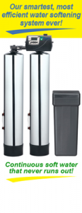
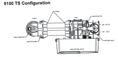
POWERHEAD ASSEMBLY
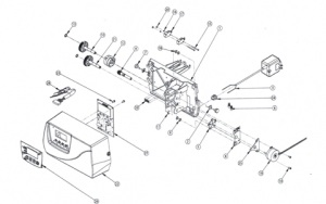
Item No. QTY Part No Description
1 1 15131 ……….. Backplate, 9000
2…………………..2 ……. 18728…………..Nut, Clip, #8-32
3…………………..1……. 19674…………. Transformer, US 24V 9.6VA
4…………………1……. 15135 ………….Gear, Drive
5…………………1……. 14869…………. Wheel, Geneva
6…………………2 ……. 40422…………. Nut, Wire, Tan
7…………………2 ……. 19367…………. Screw, Designer Cover, Thumb
8…………………1……. 43085…………. Label, Shaft Position
9…………………2 ……. 14917…………. Retaining Ring, External
10………………1……. 15133…………. Drive GearAssembly – Upper
11 ……………..1……. 15810…………. Retaining Ring
12……………..1 ……. 43091 ………… Cam, Triple 9100 TS
13………………2……. 15372…………….Washer, Thrust
14……………….1……. 14430…………….Screw, Hex Washer Head
15……………….2 ……. 19160…………. Screw, #6-32 x 318 Pan Head
16………………2 ……. 15172……………Scrw, Flat Head
Item No QTY Part No Description
17………………..2 ……. 10340…………. Washer, Lock #4, Zinc
18……………….1……. 16433…………….Switch, Micro Low DB
19………………1……. 10218…………. Switch, Micro
20………………..2 ……. 15692…………. Washer, Plain, 3/8″
21…………………2 ……. 10302…………. Insulator, Limit Switch
22…………………1……. 18737…………. Drive Motor -24V, 50-60 Hz
23………………….2 ……. 10339…………..Nut, Hex, 4-40 Zinc Plated
24…………………1 15134…………….Drive Gear Assembly – Lower
25…………………1……. 43006…………….Cover, 9100 TS
26…………………1……. 43035…………….PCB, 9100 TS
27………………..2 ……. 17020…………….Screw, STL. Hex WSH, 6-20 x 3/8
28………………..1……. 13547…………….Strain Relief, Cord
29…………………1……. 42296-10………..Plate, Adapter, Motor Kit
30…………..1 ……. 43056…………….Label, Overlay, 9100 TS
31 …………..1 ……. 43112…………….Label, Sensor Wires 9lOOTS
9100 TS Upflow
9100 CONTROL VALVE ASSEMBLY
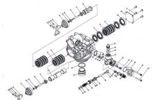
Item No. QTY Part No Description
1 ….1… 40686 ……… Valve Body Assy, 9100
2………………….16 …… 13242……………Seal, 5600
3…………………12 …… 14241 …………..Spacer
4……………….1 ……. 16595 ….. . ……….Spacer, 9000
5………………4 ……. 15331 …………….Screw, Hex Washer Head
6……………..1 ……. 14914…………….Piston, 9000, Upper
7……………….2 ……. 14309…………….Retainer, Piston Rod
8…………….2 ……. 14919…………….Piston, Rod, Upper
9…………….2 ……. 13243…………….Plug, End, 5600
10…………..2 ……. 13008…………….Retainer, End Plug Seal
11 …………..2 ……. 10209 …………….Quad Ring, -01O
12…………..1 ……. 14921 …………….Link, Piston Rod
13…………….2 ……. 11335…………….Screw, #4-40
14……………..2 ……. 17020…………….Screw, STL. Hex WSH, 6-20 x3/8
15……………….2 ……. 13363…………….Washer, Hague Drive
16……………..1 ……. 28170…………….Piston Lower, 9100T5
17……………..1 ……. 15019…………….Link, Piston Rod, 9000/9500
18……………..1 ……. 41500 …………….0-ring, 9100 Drain
19……………..1 ……. 15215…………….Body, Injector, 9000
20……………..2 ……. 13301 …………….0-nng,-011
21…………….1 ……. 1091 3-1…………Nozzle, Injector, #1, Natural
22…………….1 ……. 10914-1 ………….Throat, Injector
23…………..1 ……. 13303…………….0-ring, -021
24…………..1 ……. 15607…………….Screw, Hex, Slotted
25…………..1 ……. 25363…………….Screw, Hex WSH HD
26…………..I ……. 15348 …………….0-ring, -563
Item No QTV Part No Description
27…………………1 13173……………. Retainer, DLFC Button
28…………..I ……. 12085……………. Washer, Flow, 1.2 gpm
29…………..1 ……. 14925……………. Brine Valve Stem, 9000
30…………..1 ……. 12626……………. Seat, Brine Valve
31…………..1 ……. 13167……………. Spacer, Brine Valve
32…………..I ……. 13165……………. Cap, Brine Valve
33…………..1 ……. 11973……………. Spring, Brine Valve
34…………..I ……. 11981-01 ……….. Ring, Retaining, S$
35…………..1 ……. 16098……………. Washer, Nylon Brine
36…………..I ……. 12977 ……………. 0-ring, -015
37…………..1 ……. 13245……………. Retainer, BLFC
38…………..1 ……. 12095……………. Washer, Flow Control, .50 gpm
39…………..I ……. 12550……………. Quad Ring, -009
40…………..2 ……. 13302 ……………. 0-ring, -014
41…………..1 ……. 13244……………. Adapter, BLFC
42…………..I ……. 13497……………. Air Disperser, Injector
45…………..1 ……. 13361 ……………. Spacer, 4600
46…………..I ……. 40538……………. Retainer, 32 mm, 0-ring Dist,
7000
47…………..1 ……. 61419……………. Kit, 1.05″ Distributor Adapter
48…………..I ……. 14906……………. Plate, End, 9000
49…………..I ……. 14928……………. Plug, End Stub, 9000
50…………..1 ….. .. 60285-01 ……….. Injector Cap Assy, 9100 TS
50…………..1 ……. 10227……………. Screen, Injector
9000/9100 BYPASS VALVE ASSEMBLY
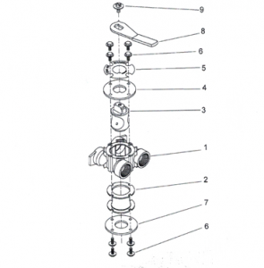
Item No. QTY Part No Description
1 …1…. 17290……………. By-Pass Body, 3/4″
……. 17290NP ……….. BY-Pass Body, 3/4″ NP, 5600
I…… 13399……………. By-Pass Body, 1″
I ……. 13399NP……….. By-Pass Body, 1″ NP
2…………….I ……. 14105……………. Seal, By-Pass, 560CD
3…………….I ……. 11972……………. Plug, By-Pass, w/Wax
4…………….I ……. 11978……………. Plate, By-Pass, Top
5…………….I ……. 13604-01……….. Label, By-Pass, Standard Mount
6…………….8 ……. 15727……………. Screw, Hex WshHd, 10-24×1/2
7…………….1 ……. 11986……………. Plate, By-Pass, Bottom
8…………….1 ……. 11979……………. Lever, By-Pass
9…………….1 ……. 11989……………. Screw, SItd Indent, 1/4- 14x 1 1/2
9100 SECOND TANK ASSEMBLY
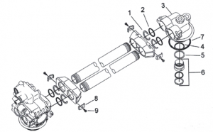
Item No . QTY Part No. Description
1 4 …….40678…………….Ring, 9100, Yoke Retainer
2…………….4 ……. 13287 ……………. 0-ring, -123
3…………….I …….14865…………….Adapter Assy, 2nd Tank, 9100
4…………….1 ……. 19054 ……………. 0-ring, -124
5…………….1 …….40538…………….Retainer, 32mm, 0-ring Dist, 7000
6…………….1 …….61419…………….Kit, 1.05′ Distributor, Adapter
7…………….1 …….18303…………….0-ring,-336
8…………….4 …….13255…………….Clip, Mounting
9…………….4 …….14202-01………..Screw, Hex Wsh Mach, 8-32 x 5/16
BYPASS VALVE ASSEMBLY
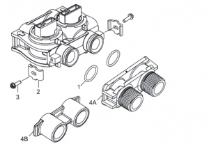
Item No. QTY Part No. Description
1…………….2 ……. 13305 ……………. 0-ring, -119
2…………….2 …….13255…………….Clip, Mounting
3…………….2 …….13314…………….Screw, Slot Ind Hex, 8-18 x.60
4A …………. I …….18706…………….Yoke, 1″, NPT, Plastic
1 …….18706-02………..Yoke, 3/4″, NPT, Plastic
4B………….1 …….41027-01………..Yoke, 3/4″, NPT, Cast, Machd
1 41026-01 ………..Yoke, 1″, NPT, Cast, Machd, SS
2300 SAFETY BRINE VALVE
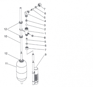
Item No. QTY Part No. Description
1…… ……….I ……. 60027-00……….. Safety Brine Valve, 2300, Less
Elbow
2…………….1 ……. 10138………….. ..Ball, 3/8″, Brass
3…………….I ……. 11566……………. Ball Stop, Slow Fill
4…………….1 ……. 10328……………. Fitting, Elbow, 90 Deg. 1/4 NPTx 3/8T
5…………….1 ……. 10332……………. Fitting, Insert, 3/8
6…………….1 ……. 10330……………. Fitting, Sleeve, 318 Celcon
7…………….1 ……. 10329……………. Fitting, Tube, 3/8 Nut, Brass
8…………….1 ……. 10186……………. Nut, Hex, 10-32
9…………….1 ……. 60002……………. Air Check, #500
10…………..1 ……. 10149……………. Rod, Float
11 …………..1 ……. 10700……………. Float Assy, Blue/White
12…………..3 ……. 10150……………. Grommet, .30 Dia
2310 SAFETY BRINE VALVE
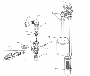
Item No. QTY Part No Description
.I ……. 19645……………. Body, Safety Brine Valve, 2310
2…………….1 ……. 19803……………. Safety Brine Valve Assy
3…………….1 ……. 19804……………. Screw, Sckt Nd, Set, 10-24 x.75
4…………….I ……. 19805……………. Nut, Hex, 10-24, Nylon Black
5…………….1 ……. 19652-01 ……….. Poppet Assy, SBV w/0-ring
6…………….1 ……. 19649……………. Flow Dispenser
7…………….1 ……. 11183 ……………. 0-ring, -017
8…………….1 ……. 19647……………. Elbow, Safety Brine Valve
9…………….2 ……. 19625 ……………. Nut Assy, 3/8″ Plastic
10…………..1 ……. 18312……………. Retainer, Drain
11…………..1 ……. 60014……………. Safety Brine Valve Assy, 2310
12…………..2 ……. 10150……………. Grommet, .30 Dia
13…………..I ……. 60068-30……….. Float Assy, 2310, w/30″ Rod
14…………..I ……. 60002-34……….. Air Check, #500
PROBE KIT
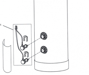
Item No. QTY Part No. Description
1 ……………….1………30212618……………….Probe/Cable/Clips Kit
TROUBLESHOOTING
Problem Cause Correction
- Water conditioner fails to regenerate. A. Electrical service to unit has been interrupted A. Assure permanent electrical service (check fuse, plug, pull chain, or switch)
- Timer is defective. B. Replace timer.
- Power failure. C. Reset time of day.
- Hard water. A. By-pass valve is open. A. Close by-pass valve.
- No salt is in brine tank. B. Add salt to brine tank and maintain salt level above water level.
- Injector screen plugged. C. Clean injector screen.
- Insufficient water flowing into brine tank. D. Check brine tank fill time and clean brine line flow control if plugged.
- Hot water tank hardness. E. Repeated flushings of the hot water tank is required.
- Leak at distributor tube. F. Make sure distributor tube is not cracked. Check 0-ring and tube pilot.
- Internal valve leak. G. Replace seals and spacers and/or piston.
- Meter is not measuring flow. H. Check meter with meter checker.
- Unit used too much salt. A. Improper salt setting. A. Check salt usage and salt setting.
- Excessive water in brine tank. B. See problem 7.
- Loss of water pressure. A. Iron buildup in line to water conditioner. A. Clean line to water conditioner.
- Iron buildup in water conditioner. B. Clean control and add mineral cleaner to mineral bed. Increase frequency of regeneration.
- Inlet of control plugged due to foreign material broken loose from pipes by recent work done on plumbing system.
- Remove piston and clean control.
- Loss of mineral through drain line. A. Air in water system. A. Assure that well system has proper air eliminator control. Check for dry well condition.
- Improperly sized drain line flow control. B. Check for proper drain rate.
- Iron in conditioned water. A. Fouled mineral bed. A. Check backwash, brine draw, and brine tank fill. Increase frequency of regeneration. Increase backwash time.
- Excessive water in brine tank. A. Plugged drain line flow control. A. Clean flow control.
- Plugged injector system. B. Clean injector and screen.
- Timer not cycling. C, Replace timer.
- Foreign material in brine valve. D. Replace brine valve seat and clean valve.
- Foreign material in brine line flow control. E. Clean brine line flow control.
- Softener fails to draw brine. A. Drain line flow control is plugged. A. Clean drain line flow control.
- Injector is plugged. B. Clean injector
- Injector screen plugged. C. Clean screen.
- Line pressure is too low. D. Increase line pressure to 20 P.S.I.
- Internal control leak E. Change seals, spacers, and piston assembly.
- Service adapter did not cycle. F. Check drive motor and switches.
- Control cycles continuously. A. Misadjusted, broken, or shorted switch. A. Determine if switch or timer is faulty and replace it, or replace complete power head.
- Drain flows continuously. A. Valve is not programming correctly. A. Check timer program and positioning of control. Replace power head assembly if not positioning
properly.
- Foreign material in control. B. Remove power head assembly and inspect bore. Remove foreign material and check control in various regeneration positions.
- Internal control leak. C. Replace seals and piston assembly.
TROUBLESHOOTING for the 9100 TS Controller
Problem Cause Solution
ERR I is displayed. Program settings have been corrupted. Press any key and reprogram Level I settings.
ERR 3 is displayed. Controller on tank 1 does not know the Wait for two minutes for the controller to return to Home
position of the camshaft. Camshaft should position. The hourglass should be flashing on the
be rotating to find Home position. display indicating the motor is running.
Camshaft on tank 1 is not turning during Check that motor is connected. Verify that motor wire
ERR 3 display. connected to motor and controller module.
Verify that Home switch sensor is connected and in place.
Verify that motor gear has engaged cam gear.
If everything is connected, try replacing in this order:
- Wire Harness, Motor, Home Switch, Sensor Assy
- Controller
Camshaft on tank 1 is turning more than five Verify that Home Switch sensor is in place and
minutes to find Home position, connected to wire.
Verify that camshaft is connected appropriately.
Verify that no dirt or rubbish is clogging any of the cam
slots.
If motor continues to rotate indefinitely, replace the
following components in this order:
- Wire Harness, Motor, Home Switch, Sensor Assy
- Controller
Regeneration starts but control shows Err3 Check that motor is connected. Verify that motor wire
before completing regeneration, harness is connected to motor and controller module.
Verify that Home Switch sensor is connected and in
place.
Verify that motor gear has engaged cam gear.
If everything is connected, try replacing in this order:
- Wire Harness, Motor, Home Switch, Sensor Assy
- Controller
ERR 4 is displayed. Hardness front detected with no water flow.
ERR 6 is displayed. Conductivity sensors’ reading out of range. Check which tank in service and check if the sensors
Defective sensors or no sensors are have been connected properly. If already connected,
connected replace conductivity sensor probes with new ones.
Check Salt Light is displayed – Press No regenerant draw or insufficient Ensure salt/regenerant is available.
the regen button to turn off the check salt light. regenerant detected during regeneration.
Check for regenerant draw.
Inspect regeneration line for leaks.
9100 TS Upflow
SERVICE ASSEMBLIES
Brine Line Flow Controls (900019100):
60022-12 ………………..BLFC, .125 GPM, 5000/560019000/9100
60022-50 ………………..BLFC, .50 GPM, 5000/5600/9000/9100
60350……………………..Brine Valve Assy, 9000/9100
Bypass Assemblies:
60040SS ………………… Bypass Valve, 5600, 3/4″ NPT
60041SS………………… Bypass Valve, 5600, 1″ NPT
60049…………………….. Bypass Plastic Assy
Injector Assemblies (9000/9100):
61 794-XXXX…………… Injector Assembly
(specify size of injector)
Tank Dia. Injector DLFC BLFC
61794-0624 ……8″ Brown #000 1.5 0.125
61794-0634 ……9″ Brown #000 2.0 0.125
61794-0644 ……10″ Brown #000 2.4 0.125
61794-0562 ……12′ Violet #00 3.5 0.5
Meter Assemblies (900019100):
15078-01 ……………….. Adapter, 1″ Coupling
60086 …………………….. Meter Assy, 5600/9000/9100, 3/4″ Std/
Range
60087 …………………….. Meter Assy, 5600/9000/9100, 3/4″, Ext
60389 …………………….. Meter Assy, 9000/9100, 1″
60389NP ………………… Meter Assy, 9000/9100, 1″, N/P
60389-20 ……………….. MeterAssy, 9000/9100, 1″, BSP/Metric
60390 …………………….. MeterAssy, 9000/9100, 1″, Ext
60390NP ………………… Meter Assy, 9000/9100, 1″, Ext, N/P
60390-20 ……………….. Meter Assy, 9000/9100, 1″, Ext/BSP/
Metric
60612…………………….. MeterAssy, 9000/9100, 1″, Std Range,
HW 150°
60612NP………………… MeterAssy, 9000/9100, 1″, Std Range,
HW 150°, NP
14038…………………….. Meter Cap Assy
15150…………………….. Meter Cap Assy, Ext
15218…………………….. Meter Cap Assy
15218NP………………… Meter Cap Assy, Std, NP
15237……………………..Meter Cap Assy, Ext
15237NP………………… Meter Cap Assy, Ext, NP
13509…………………….. Impeller, Meter
13509-01 ……………….. Impeller, Celcon, HW 150°
Piston, Seal & Spacer Kits:
61785 …………………….. 9IOOTS Upper Piston Kit
61786……………………..9100TS Lower Piston Kit
Second Tank Assemblies (9000):
14202-01 ………………..Screw, Hex Wsh Mach, 8-32 x 5/16 18-8
S.S.
13255…………………….. Clip, Mounting
15078-01 ……………….. AdapterAssy, 1″ Coupling
14864-01 ……………….. Adapter, 9000/9100, 2nd Tank, Machd
w/0-rings
14864-01 NP ……………Adapter, 9000/9100, 2nd Tank, Machd,
NP
15823-06 ……………….. Yoke Assy, 6″ Tank & 6″ Tube
15823-06NP ……………Yoke Assy, 6″ Tank, NP 6″ Tubes
15823-12 ……………….. Yoke Assy, 6″- 12″ Tank, 8 1/2 Tube
15823-12NP ……………Yoke Assy, 6″- 12″ Tank, NP 8 1/2″
Tubes
15823-14 ……………….. Yoke Assy, 14″ Tank, 101/2″ Tube
15823-I4NP …………… Yoke Assy, 14″ Tank, NP 10 1/2″ Tube
15823-16 ……………….. Yoke Assy, 16″ Tank, 12 1/2″ Tube
15823-16NP ……………Yoke Assy, 16″ Tank, NP 12 1/2″ Tube
Second Tank Assemblies (9100):
60425-12………………..Tube Assy, 9100, 6-12″ Tanks
60425-16………………..Tube Assy, 9100, 13-16″ Tanks
14865……………………..Adapter Assy, 2nd Tank, 9100
61419……………………..Kit, 1.05″ Distributor Adapter
Tools:
12763……………………..Stuffer Tool Assy, 5600/9000
13061……………………..PullerAssy, Port Ring
13759……………………..Tool, DLFC Retainer
Valve Body Assembly (9100):
40688……………………..Valve Body Assy, 9100
18303 …………………….. 0-ring, -336 18569……………………..Retainer, Tank Seal
Cover Assembly (91 OOTS):
61787 …………………….. Cover Assembly, 9100TS
This web page is being written by:
Respectfully,
Brian Hayden Boyett BS, MWS, CI
General Manager, Boyett’s Family Rayne Water Conditioning
Office: (480) 969-7251
Cell: (602) 291-4157
This email address is being protected from spambots. You need JavaScript enabled to view it.This email address is being protected from spambots. You need JavaScript enabled to view it.
This image is a water heater – heating element that was given to Johnny by a customer in Apache Junction. This is after one year.
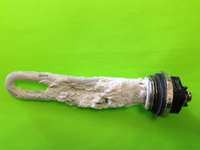
The white material is calcium and magnesium that has accumulated on this heating element. With soft water (a unit that is functioning correctly) – there will be no white material present on this heating element.
These are the Major cities and zip codes served by Rayne Water of Arizona:
85086 Anthem, AZ; 85119 – 85120 Apache Junction, AZ; 85323 – 85392 Avondale, AZ; 85326 – 85396 Buckeye, AZ; 85377 Carefree, AZ; 85122 – 85193 – 85194 Casa Grande, AZ; 85327 – 85331 Cave Creek, AZ; 85224 – 85225- 85226 – 85244 – 85246 – 85248 – 85249 Chandler, AZ; 85142 Chandler Heights, AZ; 85128 Coolidge, AZ; 85086 Desert Hills, AZ; 85192 Dudleyville, AZ; 85122 Eleven Mile Corner, AZ; 85335 El Mirage, AZ; 85131 Eloy, AZ; 85132 Florence, AZ; 85264 Fort McDowell, AZ; 85268 – 85269 Fountain Hills, AZ; 85233 – 85234 – 85295 – 85296 – 85297 – 85298 Gilbert, AZ; 85301 – 85302 – 85303 – 85304 – 85305 – 85306 – 85307 – 85308 – 85310 – 85311 – 85312 Glendale, AZ; 85309 Glendale Luke AFB, AZ; 85118 Gold Canyon, AZ; 85338 – 85395 Goodyear, AZ; 85283 Guadalupe, AZ; 85236 Higley, AZ; 85137 Kearny, AZ; 85339 Laveen, AZ; 85340 Litchfield Park, AZ; 85138 – 85139 Maricopa, AZ; 85201 – 85202 – 85203 – 85204 – 85205 – 85206 – 85207 – 85208 – 85209 – 85210 – 85211 – 85212 – 85213 – 85214 – 85215 – 85274 – 85275 Mesa, AZ; 85139 Mobile, AZ; 85087 New River, AZ; 85253 Paradise Valley, AZ; 85345 – 85380 – 85381 – 85382 – 85383 – 85385 Peoria, AZ; 85001 – 85002 – 85003 – 85004 – 85005 – 85006 – 85007 – 85008 – 85009 – 85010 – 85011 – 85012 – 85013 – 85014 – 85015 – 85016 – 85017 – 85018 – 85019 – 85020 – 85021 – 85022 – 85023 – 85024 – 85025 – 85026 – 85027 – 85028 – 85029 – 85030 – 85031 – 85032 – 85033 – 85034 – 85035 – 85037 – 85040 – 85041 – 85042 – 85043 – 85044 – 85045 – 85048 – 85050 – 85051 – 85053 – 85054 – 85083 – 85085 – 85086 Phoenix, AZ; 85142 Queen Creek, AZ; 85118 Queen Valley, AZ; 85145 Red Rock, AZ; 85263 Rio Verde, AZ; 85140 – 85143 San Tan Valley, AZ; 85250 – 85251 – 85252 – 85254 85255 – 85256 – 85257 – 85258 – 85259 – 85260 – 85261 – 85262 – 85266 – 85267 – 85271 Scottsdale, AZ; 85172 Stanfield, AZ; 85351 – 85372 – 85373 Sun City, AZ; 85375 – 85376 Sun City West, AZ; 85248 Sun Lakes, AZ; 85173 Superior, AZ; 85118 Superstition Mountain, AZ; 85374 – 85378 – 85379 – 85387 – 85388 Surprise, AZ; 85281 – 85282 – 85283 – 85284 Tempe, AZ; 85353 Tolleson, AZ; 85131 Toltec, AZ; 85354 Tonopah, AZ; 85190 Tortilla Flat, AZ; 85191 Valley Farms, AZ; 85355 Waddell, AZ; 85390 Wickenburg, AZ; 85192 Winkelman, AZ; 85361 Wittman, AZ; 85363 Youngtown, AZ and surrounding areas
Boyett’s Family will always be ready to serve you. Just call (480) 969-7251 when you need us to take action.

If you ever need anything – just let us know.